


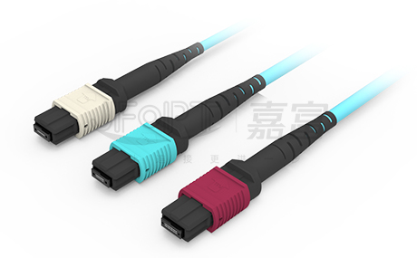
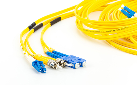
Fiber optic patch cables are fiber optic connectors used to connect optical cables and equipment or fiber optic devices. They come in various specifications and are connected by flanges at both ends, eliminating the need for fusion splicing and facilitating replacement and maintenance.

Q
What do the various diameters and outer diameter parameters in fiber optic patch cables represent?

Q
How is polarization maintained in polarization-maintaining fiber optic patch cables?
Q
Is the extinction ratio parameter of polarization-maintaining fiber optic patch cables the same as the extinction ratio of polarizers?
Q
When using polarization-maintaining fiber optic patch cables, does the polarization direction of the incident light have to align with the slow axis to maintain polarization?
Q
What is the damage threshold of fiber optic patch cables?
These parameters are related to the structure of the optical fiber.
Exploring the internal structure of optical fiber, the interpretation of various parameters is as follows:
Core Diameter: The core is the medium through which the optical beam actually propagates in the fiber optic cable. It is typically made of a high refractive index material, with a physical diameter usually ranging between 2 μm to 10 μm. The shorter the wavelength, the smaller the core diameter.
Mode Field Diameter (MFD): Fiber optic cables utilize the principle of total internal reflection. However, in practice, the optical beam penetrates the boundary and travels a certain distance in the low refractive index medium (known as the evanescent wave) before reflecting back into the high refractive index medium. The depth of penetration is wavelength-dependent. Therefore, the actual size of the optical spot is larger than the core diameter, and this actual size is termed the mode field diameter. It's important to note that the mode field diameter is not the physical size of the core diameter.
Cladding Diameter: The cladding is the medium adjacent to the core, forming a boundary between high and low refractive indices, enabling total internal reflection of light within the core. Its diameter represents its physical size.
Coating Diameter: Since both the core and cladding are made of glass material and are prone to damage, they are typically coated with a layer of resin to enhance their toughness. This layer of resin, known as the coating, has a diameter equal to the coating diameter.
Sheath Diameter: Even with the coating, optical fibers are susceptible to breakage under external forces. To better protect the optical fiber and adapt to usage in complex environments, additional plastic or metal jackets are often added to the exterior of the fiber. The diameter of these jackets represents their physical size. Common options include 0.9 mm, 2 mm, 3 mm, and 6 mm plastic protective jackets, or 3 mm and 6 mm stainless steel protective jackets.
All these diameters are measured as outer diameters.
By introducing stress rods to apply stress and achieve stress equilibrium within the fiber, thus making the polarization changes during transmission controllable.
In theory, single-mode fibers with a circular core should not exhibit birefringence, and their polarization state should remain unchanged during propagation. However, in practical production, external influences such as uneven fiber diameter or bending may lead to the occurrence of birefringence. Any external disturbances, such as bending, vibration, temperature changes, etc., may cause irregular changes in the polarization state of light during transmission.

Polarization-maintaining fibers are designed to maintain internal stress balance within the fiber, keeping the birefringence effect unchanged and generating fixed fast and slow axes to ensure stable polarization during transmission. The commonly used method involves introducing symmetrically asymmetric stress into the fiber core by adding stress rods containing two improved glass components on both sides of the fiber core. Stress-induced polarization-maintaining fibers utilize the difference in thermal expansion coefficients between the embedded stress rods and the fiber core, generating thermal stress that leads to changes in the material's refractive index, thereby producing birefringence effects.
Polarization-maintaining fibers are designed to maintain internal stress balance within the fiber, keeping the birefringence effect unchanged and generating fixed fast and slow axes to ensure stable polarization during transmission. The commonly used method involves introducing symmetrically asymmetric stress into the fiber core by adding stress rods containing two improved glass components on both sides of the fiber core. Stress-induced polarization-maintaining fibers utilize the difference in thermal expansion coefficients between the embedded stress rods and the fiber core, generating thermal stress that leads to changes in the material's refractive index, thereby producing birefringence effects.
The definition of extinction ratio is the same, but polarization-maintaining fiber optic patch cables and polarizers serve different functions.
The extinction ratio of polarization-maintaining fiber optic patch cables refers to the reference value of the extinction ratio maintained by highly extinguished polarized light after transmission, which is generally lower than the incident light. Its function is to maintain the original characteristics. On the other hand, polarizers convert low extinction ratio light into polarized light with the same high extinction ratio as the polarizer, focusing more on optimization.

Currently, the most common polarization-maintaining fiber optic patch cables on the market are Panda-type polarization-maintaining fibers, aligned with the slow axis and the Key, as shown in the diagram below. When the polarization direction of polarized light is aligned with one axis, the polarized component distributed to the other axis is minimal, thus maintaining the polarization state of the transmitted light. At this point, the extinction ratio (ER) parameter is introduced to reflect the quality of maintaining the polarization state of the fiber. When the polarization direction of polarized light is aligned with one of the fast and slow axes, two orthogonal polarization modes are generated after passing through the component. The ratio of the polarization component along the original direction axis to the polarization component along the perpendicular direction is the extinction ratio. The extinction ratio is an important parameter for measuring the quality of polarizers. The higher the extinction ratio, the better the quality of the polarizer.
No. Aligning the polarization direction of the incident light with either the fast or slow axis of the patch cable can achieve polarization maintenance, but there may be differences in transmission speed.
The damage threshold depends on the usage scenario. The factors limiting the power usage of the fiber mainly come from the connectors.

The structure at the fiber interface includes bare fiber (the resin coating layer is removed, leaving only the cladding and core), epoxy resin adhesive, and ceramic ferrule. Due to the limitations of connector alignment accuracy, it is impossible for the fiber cores to be perfectly aligned, leading to a certain degree of misalignment. This misalignment can result in some light not being coupled into the core for transmission but being refracted outside the fiber and absorbed by the epoxy resin adhesive. As the optical power increases, the leaked optical power also increases, causing the adhesive to absorb the light energy and generate high temperatures. At high temperatures, the adhesive may shrink, increasing the error in core alignment, thereby causing more light beams to refract outside the fiber cladding. In extreme cases, the adhesive may melt or evaporate, condensing on the fiber end face, blocking the optical path, and even causing combustion of the fiber end face.

When using fiber flange-assisted fiber optic patch cable docking, for fiber optic patch cables with operating wavelengths at or above 780 nm, the maximum allowable power is 300 mW; whereas for fiber optic patch cables with wavelengths below 780 nm, the maximum safe power is 50 mW. This is because epoxy resin absorbs more short-wavelength light, and at the same time, the core diameter of fibers operating at short wavelengths is smaller. With the same alignment coupling accuracy error, a higher proportion of leaked light energy occurs. When the fiber is used for output or the connectors are removed for fusion splicing using a fiber fusion splicer, the power can reach over 1 W.


 Ann
Ann


