When installing connectors on the end faces of fiber optic patch cords, inevitable return loss occurs due to reflections from the light source. Excessive light loss can damage the laser light source and interrupt signal transmission. To ensure better contact between the end faces of two fiber optic patch cords, the ferrules at the ends of the fiber optic patch cords are typically polished into different structures.

Why are fiber optic patch cords polished?


The polishing methods for fiber optic patch cords are?


Differences in Polishing Methods for Fiber Optic Patch Cords?


To ensure the stability and reliability of optical signal transmission, the ferrules at the ends of fiber optic patch cords are typically polished. This is because when connectors are installed on the end faces of fiber optic cables, reflections from the light source occur, resulting in return loss. Severe light loss can not only damage the laser light source but also potentially interrupt signal transmission. By polishing the ferrules at the ends of fiber optic patch cords, they can be made smoother, reducing air gaps upon contact, improving the efficiency of optical signal transmission, reducing return loss, and thus ensuring a good connection between fiber optics.


Typically, there are three polishing methods for fiber optic end faces: PC, UPC, and APC:


PC (Physical Contact) involves using a slight convex surface polishing technique with microspheres to create a slightly convex surface on the ferrule.
UPC (Ultra Physical Contact) builds upon PC by further optimizing the end-face polishing and surface cleanliness, resulting in a more dome-shaped end face.
APC (Angled Physical Contact) involves polishing the fiber optic end face into an 8° angled surface.


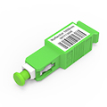
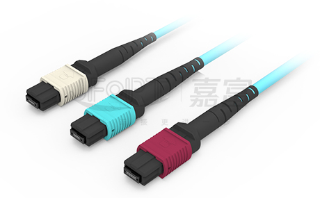
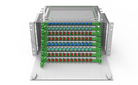
①Color Difference: APC connectors are typically green, while UPC/PC connectors are usually blue.
②Insertion Loss: Insertion loss refers to the decibel difference between the output optical power and the input optical power after the optical signal passes through the fiber optic patch cord. Generally, the typical insertion loss of PC, UPC, and APC connectors should be less than 0.3dB. Due to smaller air gaps, UPC/PC connectors typically achieve lower insertion loss more easily.
③Return Loss: Return loss refers to the decibel ratio of the power of the backward-reflected light to the power of the incident light at the connection point of the fiber optic patch cord. Return loss is usually represented in negative dB values, with higher values being preferable. The return loss of PC connectors is typically around -40dB, UPC connectors usually achieve around -55dB, and the industrial standard for APC is -60dB. APC connectors exhibit better return loss than UPC connectors, while UPC connectors outperform PC connectors.
④Application Scenarios: PC connectors are the most common polishing method for fiber optic patch cords, mainly used in telecommunications operator equipment. UPC connectors are typically used in Ethernet network equipment, digital, cable television, and telephone systems, among other scenarios.
APC is typically suitable for optical RF applications in the high wavelength range, as well as for passive optical applications such as PON network structures or passive optical LANs.


Due to the 8-degree angled end face of APC, it cannot be mated with UPC connectors, as doing so would degrade the connector's performance. However, both PC and UPC fiber end faces are flat, and while the quality of polishing may vary, mismatching PC and UPC does not typically result in permanent physical damage to the connectors.








 Ann
Ann


