


|
Product Model
|
JFTSM-SFPCO-01A-01-RJ45-SGMII
|
Manufacturer brand
|
JFOPT
|
|
Package Type
|
SFP
|
Interface Type
|
RJ45
|
|
Max Data Rate
|
125Mbps
|
10G Effective transmission distance(OM4)
|
100m
|
|
Hot-Pluggable SFP
|
YES
|
Operating voltage
|
3.3V
|
|
Power Consumption
|
-
|
Protocols
|
SFP MSA IEEE Std 802.3
|
|
Operating Temperature(Commercial)
|
0℃~+70℃
|
Storage Temperature(Commercial)
|
-40℃~+85℃
|
|
Operating Temperature(Industrial)
|
-40℃~+85℃
|
Storage Temperature(Industrial)
|
-40℃~+85℃
|
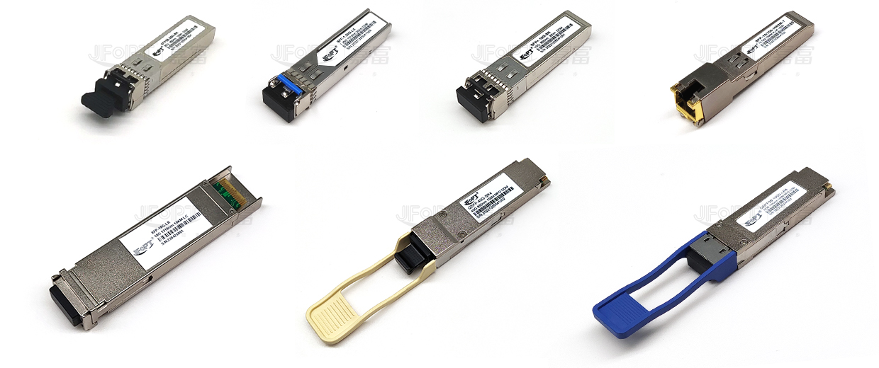
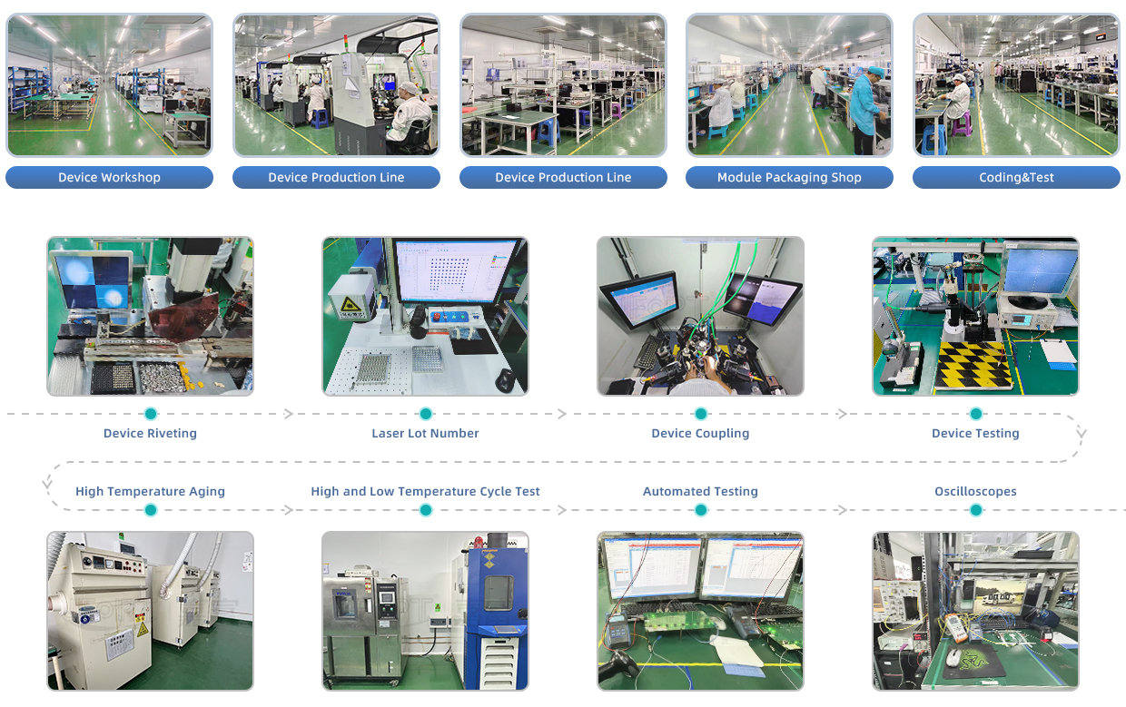
JFOPT continues to invest in optical transceiver production, covering a full range of optical transceiver such as 1*9, SFP, 10G, 25G, 100G, 200G, 400G, 800G GPON/EPON/XG/XGSPON OLT transceiver. At the same time, our company provides TOSA, ROSA, BOSA semi-finished device solutions for the downstream peer. JFOPT's production line has a daily production capacity of 10,000 optical transceivers and 20,000 optical devices. In addition, JFOPT's optical transceiver have industry-leading high temperature resistance and anti-interference capability, and are widely used in computing centers, operators, traffic security, power facilities and other industries.
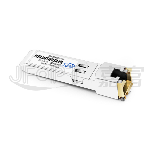
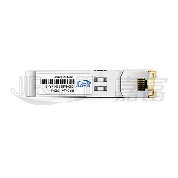
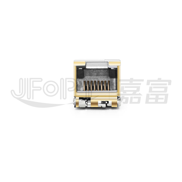
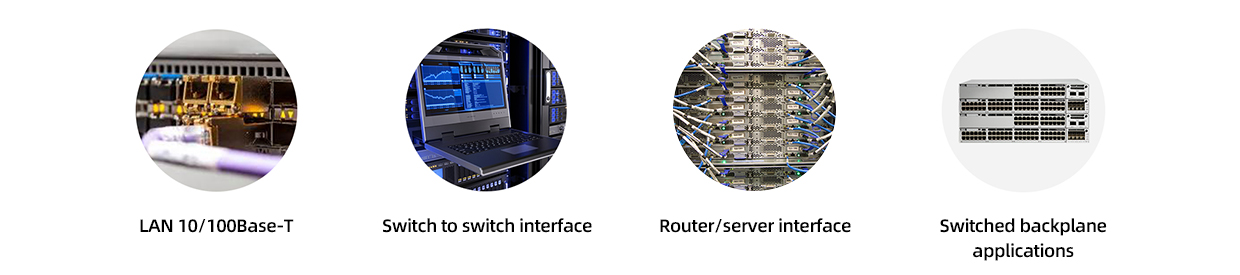
The JFOPT SFP-Copper 10/100BASE-T 100m RJ45 transceiver is a compact, high-performance, and cost-effective Small Form Pluggable (SFP) module, designed for 10/100BASE-T applications. Built on the SFP Multi-Source Agreement (MSA) standard, this transceiver complies with IEEE 802.3-2002 and IEEE 802.3u specifications, supporting up to 100 Mbps data transmission over 100 meters via unshielded twisted-pair category-5 cable. It also offers essential scrambling and descrambling between 100Base-TX and 100Base-FX formats, along with intelligent auto-negotiation for seamless 100BASE-T operation in host systems.
| Support 10/100BASE-T operation in host systems | For 100m reach over Cat 5 UTP cable | ||||||||
| Hot-Pluggable SFP Footprint | Fully metallic enclosure for low EMI | ||||||||
| Low power dissipation | Compact RJ-45 connector assembly | ||||||||
| Detailed product information in EEPROM | Operating case temperature Standard :0C~70C Industrial :-40C~85C |
||||||||
| Compliant with SFP MSA | Compliant with IEEE Std 802.3 |

| Part No. | Data Rate | Link Type | Connector | LOS Function | Distance | Tempe. | ||
| JFTSM-SFPCO-01A-01-RJ45-SGMII | 10/100M | Cat5 | RJ45 | With | 100m | Standard | ||
| Parameter | Symbol | Min. | Typ | Max. | ||||
| Maximum supply voltage | Vcc | -0.5 | - | 4.0 | ||||
| Storage temperature | TS | -40 | - | 85 | ||||
| Parameter | Symbol | Min | Typ | Max | Units | Ref. | ||
| Operating case temperature | Tc | 0 | - | 70 | °C | Standard | ||
| -40 | - | 85 | Industrial | |||||
| Supply voltage | Vcc | 3.15 | 3.3 | 3.45 | V | - | ||
| Parameter | Symbol | Min | Typ | Max | Units | Notes/Conditions | ||
| +3.3 Volt Electrical Power Interface |
||||||||
| Supply current | Icc | - | 170 | 300 | mA | - | ||
| Input voltage | Vcc | 3.13 | 3.3 | 3.47 | V | - | ||
| Surge vurrent | Isurge | - | - | 30 | mA | - | ||
Low-Speed Signals, Electronic Characteristics |
||||||||
| SFP output low | VOL | 0 | - | 0.5 | V | 4.7k to 10k pull-up to host_Vcc, measured at host side of connector | ||
| SFP output high | VOH | host_Vcc-0.5 | - | host_Vcc+0.3 | V | 4.7k to 10k pull-up to host_Vcc, measured at host side of connector | ||
| SFP input low | VIL | 0 | - | 0.8 | V | 4.7k to 10k pull-up to Vcc, measured at SFP side of connector | ||
| SFP input high | VIH | 2 | - | Vcc + 0.3 | V | 4.7k to 10k pull-up to Vcc, measured at SFP side of connector | ||
High-Speed Electrical Interface, Transmission Line-SFP |
||||||||
| Line baud rates | fL | - | 125 | - | MHz | MLT-3 encoding per IEEE802.3u | ||
| TX output impedance | Zout, TX |
-
|
100 | - | Ohm | Differential, AC coupled Internally | ||
| RX input impedance | Zin, RX | - | 100 | - | Ohm | Differential, AC coupled Internally | ||
High-Speed Electrical Interface, Host-SFP |
||||||||
| Single ended data input swing | Vin | 250 | - | 1200 | mV | Single ended | ||
| Single ended data output swing | Vout | 300 | - | 1000 | mV | Single ended | ||
| Rise/Fall time | Tr, Tf | - | 3 | - | nsec | 20%-80% | ||
| TX Iinput impedance | Zin | - | 50 | - | Ohm | Single ended | ||
| RX output impedance | Zout | - | 50 | - | Ohm | Single ended | ||
| Parameter | Symbol | Min | Typ | Max | Units | Notes/Conditions | ||
| Data rate | JFTSM-SFPCO-01A-01-RJ45-SGMII | - | 10 | - | Mbps | - | ||
| - | 125 | - | - | |||||
| Distance | - | - | - | 100 | m | Category 5 UTP. BER <10-12 | ||
| Pin No. | Name | Function | Plug Seq. | Notes | ||||
| 1 | VeeT | Transmitter ground | 1 | - | ||||
| 2 | TX fault | Transmitter fault indication | 3 | 1 | ||||
| 3 | TX disable | Transmitter disable | 3 | 2 | ||||
| 4 | MOD-DEF2 | Module definition 2 | 3 | 3 | ||||
| 5 | MOD-DEF1 | Module definition 1 | 3 | 3 | ||||
| 6 | MOD-DEF0 | Module definition 0 | 3 | 3 | ||||
| 7 | Rate select | Not connected | 3 | - | ||||
| 8 | LOS | Los of signal | 3 | 4 | ||||
| 9 | VeeR | Receiver ground | 1 | - | ||||
| 10 | VeeR | Receiver ground | 1 | - | ||||
| 11 | VeeR | Receiver ground | 1 | - | ||||
| 12 | RD- | Inv. received data out | 3 | 5 | ||||
| 13 | RD+ | Received data out | 3 | 5 | ||||
| 14 | VeeR | Receiver ground | 1 | - | ||||
| 15 | VccR | Receiver power | 2 | 6 | ||||
| 16 | VccT | Transmitter power | 2 | 6 | ||||
| 17 | VeeT | Transmitter ground | 1 | - | ||||
| 18 | TD+ | Transmit data in | 3 | 7 | ||||
| 19 | TD- | Inv. transmit data in | 3 | 7 | ||||
| 20 | VeeT | Transmitter ground | 1 | - | ||||
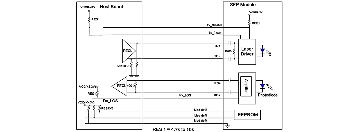
The following is the Diagram of host board connector pin numbers and names

JFOPT Copper SFP support the 2-wire serial communication protocol defined in the SFP MSA. These SFP use a 128 byte EEPROM with an address of A0H.
Accessing Serial ID Memory uses the 2 wire address 1010000X (A0H). Memory Contents of Serial ID are shown in Table 1.
|
Table 1 Serial ID Memory Contents |
||||||||
| Addr. | Size (Bytes) |
Name of Field | Hex | Description | ||||
BASE ID FIELDS |
||||||||
| 0 | 1 | Identifier | 03 | SFP | ||||
| 1 | 1 | Ext. Identifier | 04 | SFP function is defined by serial ID only | ||||
| 2 | 1 | Connector | 22 | RJ-45 | ||||
| 3- 10 | 8 | Transceiver | 00 00 00 20 00 00 00 00 | 100BASE-FX | ||||
| 11 | 1 | Encoding | 02 | 4B5B | ||||
| 12 | 1 | BR, Nominal | 01 | 100M | ||||
| 13 | 1 | Reserved | 00 | - | ||||
| 14 | 1 | Length (9µm)km | 00 | Transceiver transmit distance |
||||
| 15 | 1 | Length(9µm)100m | 00 | |||||
| 16 | 1 | Length (50µm) 10m | 00 | |||||
| 17 | 1 | Length(62.5µm)10m | 00 | |||||
| 18 | 1 | Length (Copper) | 64 | 100m | ||||
| 19 | 1 | Reserved | 00 | - | ||||
| 20-35 | 16 | Vendor name | XX XX XX XX XX XX XX XX 20 20 20 20 20 20 20 20 |
Vendor name (ASCII) | ||||
| 36 | 1 | Reserved | 00 | - | ||||
| 37-39 | 3 | Vendor OUI | XX XX XX | - | ||||
| 40-55 | 16 | Vendor PN | Transceiver part number | |||||
| 56-59 | 4 | Vendor rev | XX XX XX XX | - | ||||
| 60-61 | 2 | Wavelength | 00 | - | ||||
| 62 | 1 | Reserved | 00 | - | ||||
| 63 | 1 | CC_BASE | Check Sum (Variable) | Check code for Base ID Fields | ||||
EXTENDED ID FIELDS |
||||||||
| 64-65 | 2 | Options | 00 00 | - | ||||
| 66 | 1 | BR,max | 00 | - | ||||
| 67 | 1 | BR,min | 00 | - | ||||
| 68-83 | 16 | Vendor SN | XX XX XX XX XX XX XX XX 20 20 20 20 20 20 20 20 |
Serial Number of transceiver (ASCII). For example“B000822” . | ||||
| 84-91 | 8 | Date code | XX XX XX XX XX XX XX XX |
Manufacture date code. For example “080405” . |
||||
| 92-94 | 3 | Reserved | XX | - | ||||
| 95 | 1 | CC_EXT | Check Sum (Variable) | Check sum for Extended ID Field. | ||||
VENDOR SPECIFIC ID FIELDS |
||||||||
| 96-127 | 32 | Vendor Specific | Read only | Depends on customer information | ||||
| 128-255 | 128 | Reserved | Read only | - | ||||


 Ann
Ann


