


| Product model | JFTSM-SFP28-25-CW-10-LCD | Manufacturer brand | JFOPT |
| Package type | SFP28 | Optical connector | Duplex LC |
| Max data rate | 25.78G | Channel data rate | 14.025Gbps |
| Effective transmission distance | 10km | ||
| Wavelength | 1270/1290/1310/1330/1350/1370/ 1470/1490/1510/1530/1550/1570nm |
Operating voltage | 3.3V |
| Fiber type | SMF | Core size | 9/125 |
| Transmitter type | DFB CWDM | Receiver type | PIN |
| TX power | 0~6dBm | Receiver sensitivity | <-14dBm |
| Digital optical monitoring(DOM) | YES | Receiver overload | - |
| Power consumption | 1.3W | Protocols | MSA,CPRI, eCPRI |
| Operating temperature(Commercial) | 0℃~+70℃ | Storage temperature(Commercial) | -40℃~+85℃ |
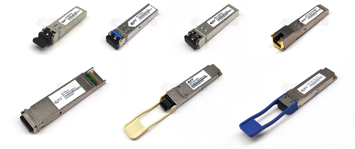
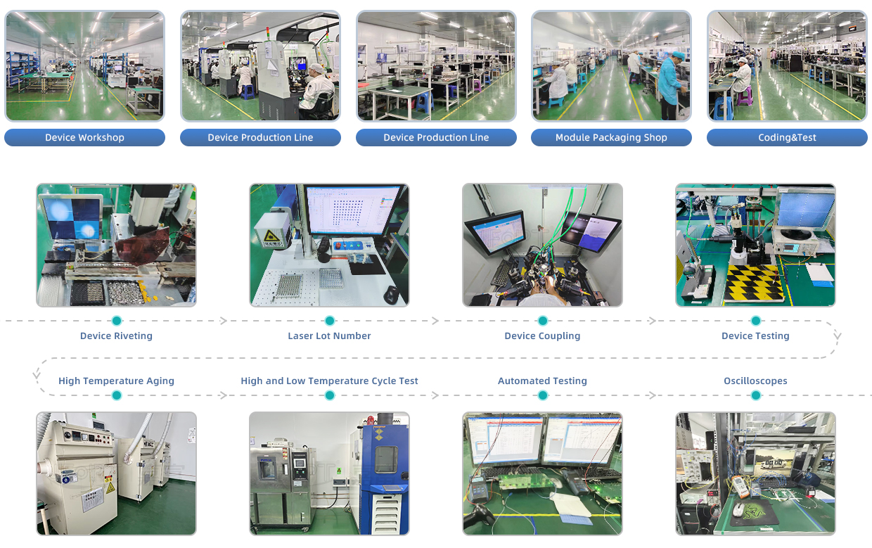
JFOPT continues to invest in optical transceiver production, covering a full range of optical transceiver such as 1*9, SFP, 10G, 25G, 100G, 200G, 400G, 800G GPON/EPON/XG/XGSPON OLT transceiver. At the same time, our company provides TOSA, ROSA, BOSA semi-finished device solutions for the downstream peer. JFOPT's production line has a daily production capacity of 10,000 optical transceivers and 20,000 optical devices. In addition, JFOPT's optical transceiver have industry-leading high temperature resistance and anti-interference capability, and are widely used in computing centers, operators, traffic security, power facilities and other industries.
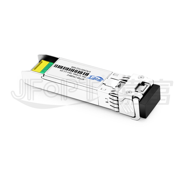
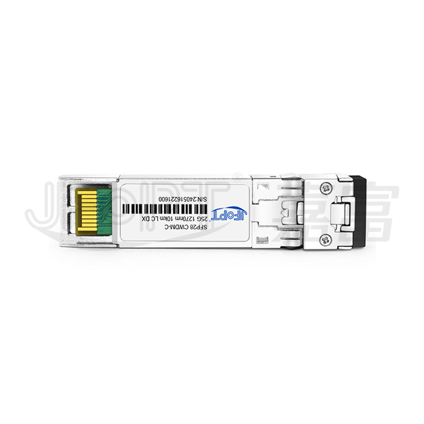
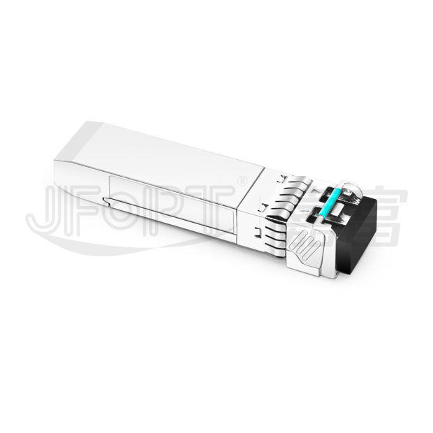
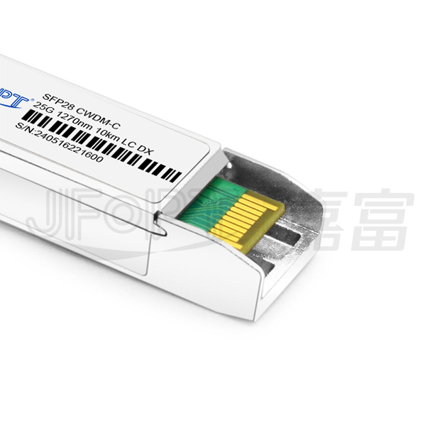
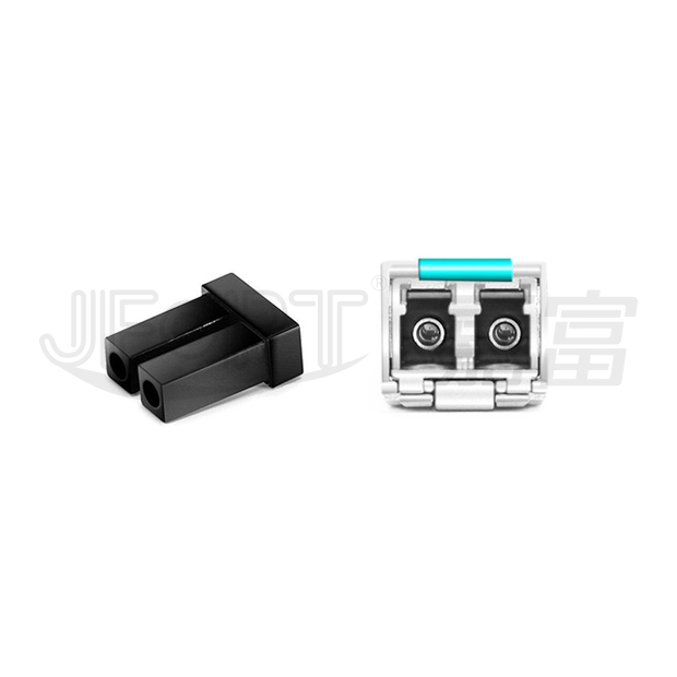
The JFOPT SFP28 25G CWDM 10km LC DX transceiver is a high-performance module designed for 25GBase-CWDM connectivity, delivering data rates of up to 25Gbps over single-mode fiber (SMF) with a range of 10km. Operating within a wavelength range of 1270nm to 1370nm and utilizing an LC duplex connector, this transceiver is ideal for 25G Ethernet, telecom, and data center applications.Fully compliant with the SFP28 MSA, CPRI, and eCPRI standards, it ensures seamless integration and reliable performance in high-speed network environments.
| Universal SFP28 MSA package with duplex LC connector | Uncool DML laser and PlN photodetector | ||||||||
| International class 1 laser safety certifled |
| 25GBASE ethernet | CPRI option 10 / eCPRI | |||||||

| Parameter | Symbol | Min. | TyP. | Max. | Unit | ||||
| Storage temperature | TS | -40 | - | 85 | °C | ||||
| Supply currnt | TS | - | - | 330 | mA | ||||
| Maximum power dissipation | PD | - | - | 1 | W | ||||
| Aggregate bit rate | ABR | 24.33 | - | 25.78 | Gb/s | ||||
| Operating distance | - | 2 | - | 10000 | m | ||||
| Parameter | Symbol | Min. | TyP. | Max. | Unit | ||||
| Operating case temperature | TOP | 0 | - | 70 | °C | ||||
| Power supply voltage | VCC | 3.13 | 3.3 | 3.46 | V | ||||
| Instantaneous peak current at hot plug | ICC_IP | - | - | 400 | mA | ||||
| Sustained peak current at hot plug | ICC_SP | - | - | 330 | mA | ||||
| Parameter | Symbol | Min. | Typ. | Max. | Unit | Note | |||
Transmitter |
|||||||||
| Nominal wavelength | λC0 | 1264.5 1284.5 1304.5 1324.5 1344.5 1364.5 |
1271 1291 1311 1331 1351 1371 |
1277.5 1297.5 1317.5 1337.5 1357.5 1377.5 |
nm | - | |||
| Side-mode suppression ratio | SMSR | 37 | - | - | dB | - | |||
| Spectral width | Δλ | - | - | 1 | nm | - | |||
| OFF_average power | POFF | - | - | -40 | dBm | - | |||
| Average optical power | POUTL | 0 | - | 6 | dBm | - | |||
| Optical modulation amplitude | OMA | 0 | - | 6 | dBm | - | |||
| Extinction ratio | ER | 3.5 | - | - | dB | - | |||
| Transmitter and dispersion penalt (1271/1291/1311nm/1331 nm) |
TDP | - | - | 3 | dB | - | |||
| Transmitter and dispersion penalty(1351/1371nm) | 4.5 | ||||||||
| Optical return loss tolerance | ORLT | - | - | 20 | dB | - | |||
| Eye mask margin | - | 10@25℃ 5@70℃&0℃ |
- | - | % | 1 | |||
| Crossing | - | 40 | 50 | 60 | % | - | |||
Receiver |
|||||||||
| Center wavelength | λC0 | 1271 | - | 1371 | nm | - | |||
| Parameter | Symbol | Min. | Typ. | Max. | Unit | Note | |||
| Overload input optical power | PMAX | 3 | - | - | dBm | - | |||
| Receiver sensitivity_OMA | BOL | - | - | -14.5 | dBm | 2 | |||
| Receiver sensitivity (OMA) | EOL | - | - | -14 | dBm | - | |||
| Optical return loss | ORL | 27 | - | - | dBm | - | |||
| Receiver reflectance | RXR | - | - | -30 | dBm | - | |||
| LOS de-assert | LOSD | - | - | -17 | dBm | - | |||
| LOS assert | LOSA | -30 | - | - | dBm | - | |||
| LOS hysteresis | - | 0.5 | - | 4 | dB | - | |||
Notes: 1 . EYE Mask Margin test conditions, sample waveform ≥1000 wfms, Hit Ratio 5E-5. 2. Measured with a PRBS 231-1 test pattern @25.78125Gbps, BER≤5E-5. |
|||||||||
| Parameter | Symbol | Min. | Typ. | Max. | Unit | ||||
| Supply voltage | VCC | 3.14 | 3.3 | 3.46 | V | ||||
| Supply current | ICC | - | - | 330 | mA | ||||
Transmitter |
|||||||||
| Input differential impedance | Rin | - | 100 | - | Ω | ||||
| Single ended data input swing | VIN | 90 | - | 450 | mVp-p | ||||
| Transmit disable voltage | VDIS | 2 | - | VCCHOST+0.3 | V | ||||
| Transmit enable voltage | VEN | VEE | - | VEE+0.8 | V | ||||
| Transmit fault assert voltage | VFA | 2.2 | - | VCCHOST+0.3 | V | ||||
| Transmitfault de-assert voltage | VFDA | VEE | - | VEE+0.4 | V | ||||
Receiver |
|||||||||
| Single ended data output swing | VOD | 225 | - | 375 | mVp-p | ||||
| LOS fault | LOS_FT | 2.2 | - | VCCHOST+0.3 | V | ||||
| LOS normal | LOS_Nor | VEE | - | VEE+0.4 | V | ||||

| Pin No. | Symbol | Logic | Description | ||||||
| 1,7,20 | VeeT | - | Connected to signal ground on the host board. | ||||||
| 2 | TX fault | LVTTL output | Module transmitter fault output | ||||||
| 3 | TX disable | LVTTL input | Module transmitter disable control | ||||||
| 4 | SDA | LVTTL input/output | 2-wire serial interface data | ||||||
| 5 | SCL | LVTTL input/output | 2-wire serial interface clock | ||||||
| 6 | MOD_ABS | - | Module absent (connected to module ground) | ||||||
| 7 | RS0 | LVTTL input | Rate select 0 (Rx): Low=CDR Bypass; high=CDR select | ||||||
| 8 | LOS | LVTTL output | Receiver loss of signal | ||||||
| 9 | RS1 | LVTTL input | Rate select 1 (Tx): Low=CDR Bypass; high=CDR select | ||||||
| 10,11,14 | VeeR | - | Connected to signal ground on the host board. | ||||||
| 12 | RD- | CML output | Receiver inverted data output, internally AC coupled and terminated. | ||||||
| 13 | RD+ | CML output | Receiver non-inverted data output, internally AC coupled and terminated. | ||||||
| 15 | VccR | - | Receiver power 3.3V supply | ||||||
| 16 | VccT | - | Transmitter power 3.3V supply | ||||||
| 18 | TD+ | CML input | Transmitter non-inverted data input, internally AC coupled and terminated. | ||||||
| 19 | TD- | LVTTL output | Transmitter inverted data Input, internally AC coupled and terminated | ||||||
| Parameter | Range | Accuracy | Unit | ||||||
DDM Accuracy |
|||||||||
| Operating case temperature | 0 to 70 | ±3 | ℃ | ||||||
| Voltage | 3.13 to 3.46 | ±3% | V | ||||||
| Tx bias current (each lane) | 20 to 80 | ±10 % | mA | ||||||
| Tx output power (each lane) | 0 to 6 | ±2 | dB | ||||||
| Rx power (each lane) | -14.5 to 3 | ±2 | dB | ||||||
| Parameter | Comments | Unit | |||||||
DDM alarm & warning threshold |
|||||||||
| Temp high alarm | 75 | ℃ | |||||||
| Temp low alarm | -5 | ℃ | |||||||
| Temp high warning | 70 | ℃ | |||||||
| Temp low warning | 0 | ℃ | |||||||
| VCC high alarm | 3.63 | V | |||||||
| VCC low alarm | 2.97 | V | |||||||
| VCC high warning | 3.46 | V | |||||||
| VCC low warning | 3.13 | V | |||||||
| Tx bias high alarm | 100 | mA | |||||||
| Tx bias low alarm | 10 | mA | |||||||
| Tx bias high warning | 80 | mA | |||||||
| Tx bias low warning | 20 | mA | |||||||
| Tx power high alarm | 8.2 | dBm | |||||||
| Tx power low alarm | -3 | dBm | |||||||
| Tx power high warning | 6 | dBm | |||||||
| Tx power low warning | 0 | dBm | |||||||
| Rx power high alarm | 5 | dBm | |||||||
| Rx power low alarm | -16.5 | dBm | |||||||
| Rx power high warning | 3 | dBm | |||||||
| Rx power low warning | -14.5 | dBm | |||||||


 Ann
Ann


