


PLC optical splitter (Planar Lightwave Circuit Splitter), also known as a planar waveguide optical splitter, is a passive device with multiple input and output ports. It is capable of distributing one or two input optical signals into multiple output signals. It is particularly suitable for passive optical networks such as FTTX, EPON, GPON, and BPON, connecting central office equipment with terminal equipment to achieve efficient optical signal distribution. The advantages of PLC optical splitters include the following points:
Simply put, a PLC optical splitter is a solution with low cost, high stability, and high reliability, with a splitting ratio of up to 1:64, which significantly surpasses the common FBT optical splitter. For more information on the differences between PLC optical splitters and FBT optical splitters, as well as selection recommendations, please visit "What are the differences between PLC optical splitters and FBT fused optical splitters?"
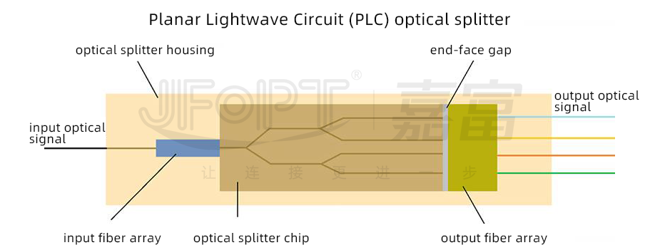
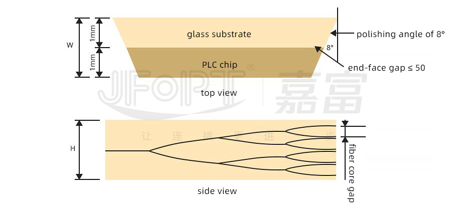
PLC optical splitters are manufactured using advanced semiconductor technology. They consist of a PLC splitter chip and multiple optical waveguide arrays (i.e., fiber arrays for input and output), with the fiber arrays connected at both ends of the PLC splitter chip. In other words, the chip is packaged with multi-channel fiber arrays at both ends, while the splitting function is performed on the chip itself. A single PLC chip can achieve splitting for up to 64 optical signals.
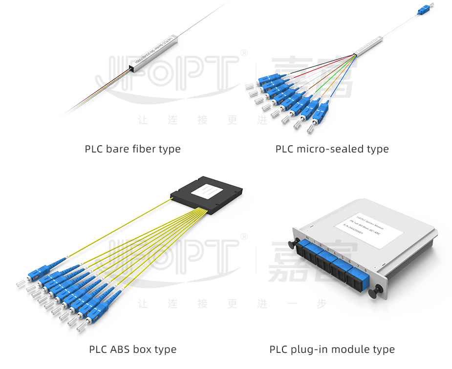
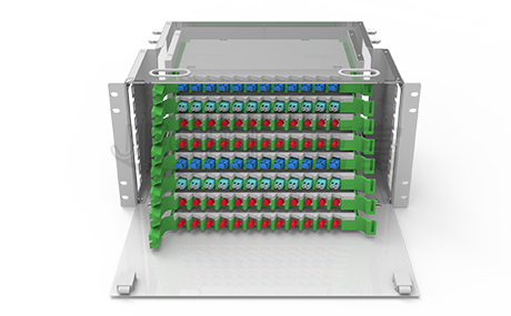
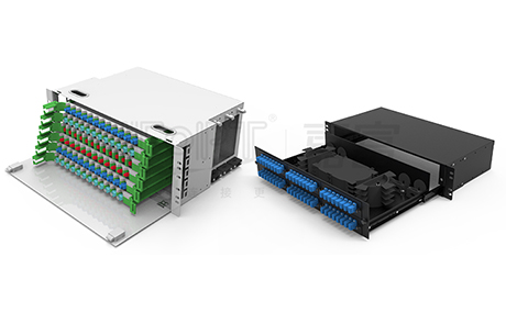
Based on the number of chips, PLC optical splitters can be categorized into 1xN and 2xN types, such as 1x4 PLC optical splitter, 1x8 PLC optical splitter, 1x16 PLC optical splitter, 2x32 PLC optical splitter, and 2x64 PLC optical splitter, among others. Additionally, depending on the packaging type, PLC optical splitters can be classified into various forms, including bare fiber type, micro steel tube type, ABS box type, with branch type, tray type, rack-mounted type, LGX optical splitter, and micro plug-in type, to meet different application needs.
In passive optical networks, PLC splitters are typically installed between the optical line terminal (OLT) and the optical network unit (ONU) or optical network terminal (ONT) near the end user. The input end of the splitter is connected to the OLT fiber link in the central office (CO), and the PLC splitter distributes the optical signal into multiple output signals, which are then transmitted to various optical network end users.
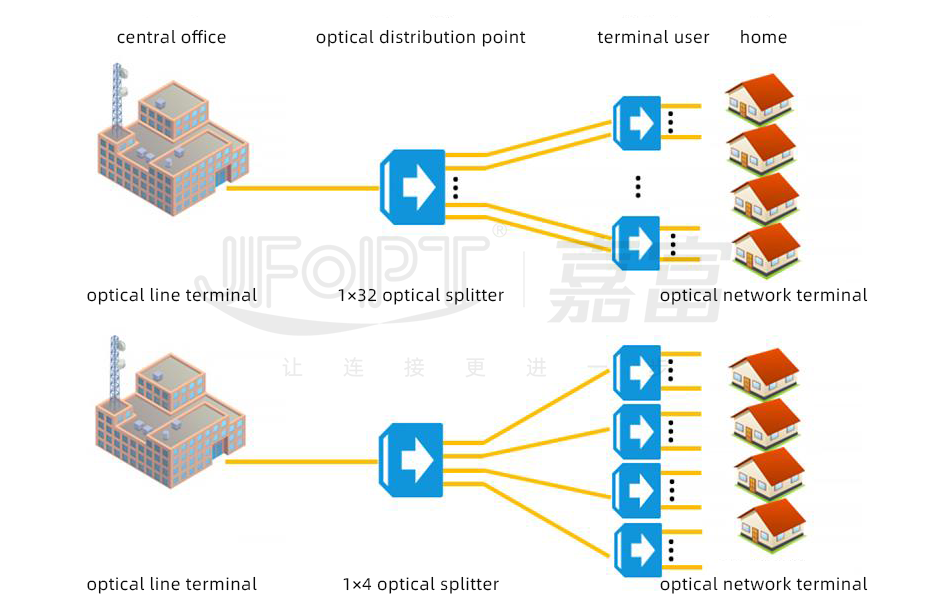
As network scale and capacity continue to expand, telecom operators need to rely on efficient and reliable PLC optical splitters to meet the growing demand for fiber links among more users. As an integrated waveguide optical power distribution device, the PLC optical splitter can significantly increase the user capacity of fiber optic networks, providing an ideal solution for network construction.


 Ann
Ann


