


| Product model | JFTSM-SFP28-25-13-03(ESR)-LCD | Manufacturer brand | JFOPT |
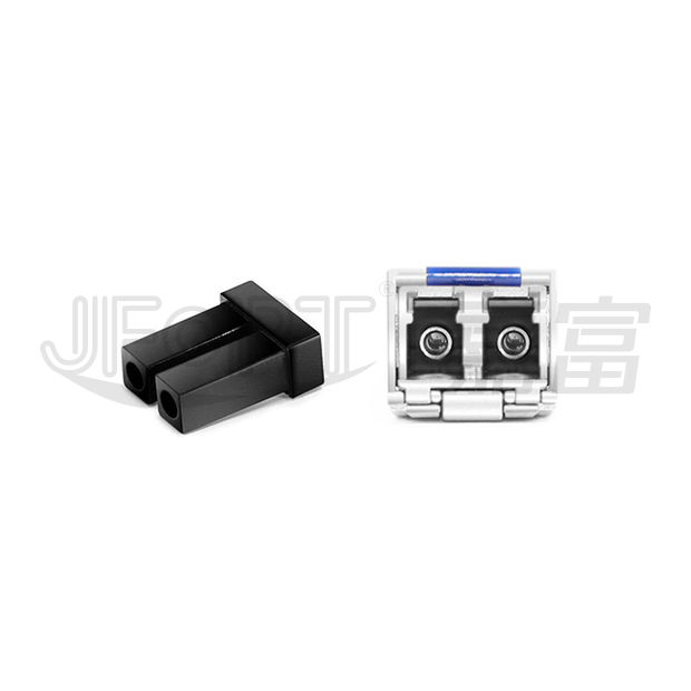
| Package type | SFP28 | Optical connector | Duplex LC |
| Max data rate | 25.78G | Channel data rate | - |
| Effective transmission distance | 300m | ||
| Wavelength | 1310nm | Operating voltage | 3.3V |
| Fiber type | SMF | Core size | 9/125 |
| Transmitter type | DFB | Receiver type | PIN |
| TX power | -5~2dBm | Receiver sensitivity | <-8.5dBm |
| Digital optical monitoring(DOM) | YES | Receiver overload | - |
| Power consumption | <1W | Protocols | SFF-8472, SFF-8024, SFF-8431, SFF-8432, IEEE 802.3 by, IEEE 802.3cc |
| Operating temperature(Commercial) | 0℃~+70℃ | Storage temperature(Commercial) | -40℃~+85℃ |
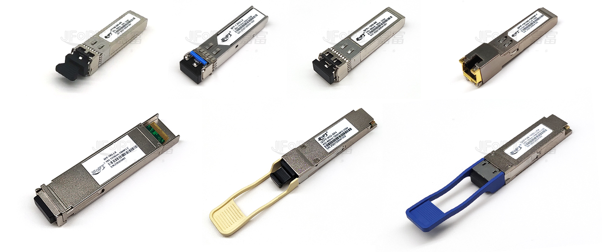
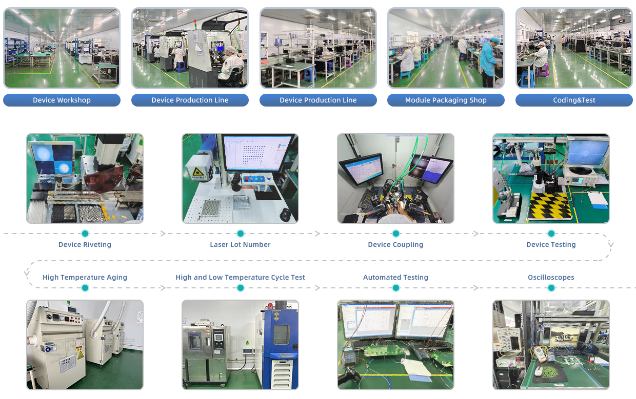
JFOPT continues to invest in optical transceiver production, covering a full range of optical transceiver such as 1*9, SFP, 10G, 25G, 100G, 200G, 400G, 800G GPON/EPON/XG/XGSPON OLT transceiver. At the same time, our company provides TOSA, ROSA, BOSA semi-finished device solutions for the downstream peer. JFOPT's production line has a daily production capacity of 10,000 optical transceivers and 20,000 optical devices. In addition, JFOPT's optical transceiver have industry-leading high temperature resistance and anti-interference capability, and are widely used in computing centers, operators, traffic security, power facilities and other industries.
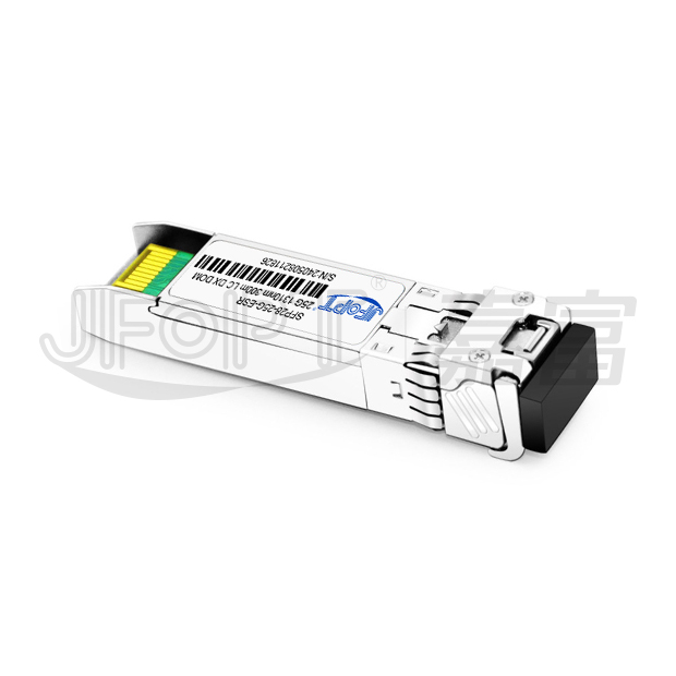
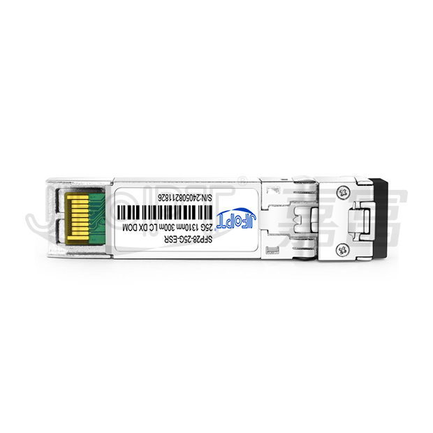
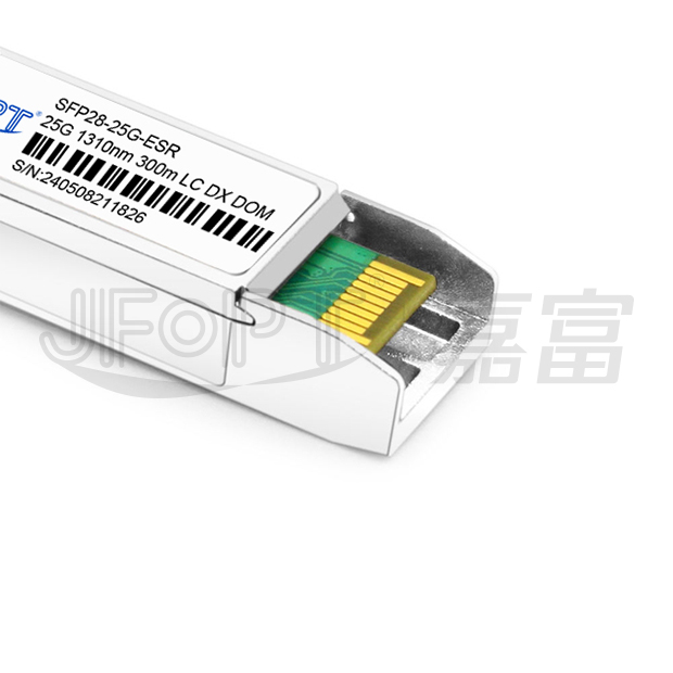
The JFOPT SFP28 25G 1310nm 300m ESR LC DX transceiver is a high-performance module designed for 25Gbps optical data transmission and reception over single-mode fiber. Equipped with a 1310nm DFB laser, it supports transmission distances of up to 300 meters.This transceiver complies with industry standards, including SFF-8472, SFF-8402, SFF-8432, and relevant sections of SFF-8431. It also features digital diagnostic functions accessible via a 2-wire serial interface, as outlined in the SFF-8472 specification.
| Built-in macom chip, max. power consumption 1W | Certified and tested in targeted switch for superior performance, quality, and reliability |
| 25GBASE-LR-S | 25G Ethernet / data center |

| Part number | Form factor | Data rate (Gb/s) |
Laser | Optical power (dBm) |
Detector | Receiver sensitivity (OMA)(dBm) |
Temp(℃) | Reach (km) |
DDM |
| JFTSM-SFP28-25-13-03(ESR)-LCD | SFP28 | 25.78125 | 1310nmDFB | -5~2 | PIN | <-8.5 | 0~70 | 0.3 | Y |
Recommended Storage conditions |
|||||||||
| Parameter | Symbol | Min. | Max. | Unit | |||||
| Storage temperature range | Ts | -45 | 85 | °C | |||||
| Relative humidity | RH | 0 | 95 | % | |||||
| Supply voltage | Vcc | -0.3 | 4.0 | V | |||||
Recommended Operating Conditions |
|||||||||
| Parameter | Symbol | Min. | Typ. | Max. | Unit | ||||
| Operating case temperature range | TOPR | 0 | - | 70 | ℃ | ||||
| Power supply voltage | Vcc | 3.14 | 3.3 | 3.46 | V | ||||
| Bit rate | BR | - | 25.78 | - | Gb/s | ||||
| Max supported link length | L | 0.3 | - | - | km | ||||
| Parameter | Symbol | Unit | Min. | Typ. | Max. | Note | |||
| Supply voltage | Vcc | V | 3.14 | 3.3 | 3.46 | - | |||
| Supply current | Icc | mA | - | 300 | - | - | |||
Transmitter |
|||||||||
| Input differential impedance | RIN | Ω | - | 100 | - | - | |||
| Single ended data input swing | VIN | mVp-p | 90 | - | 450 | - | |||
| Transmit disable voltage | VDIS | V | 2 | - | VCCHOST | - | |||
| Transmit enable voltage | VEN | V | VEE | - | VEE+0.8 | - | |||
| Transmit fault assert voltage | VFA | V | 2.2 | - | VCCHOST | - | |||
| Transmit fault de-assert voltage | VFDA | V | VEE | - | VEE+0.4 | - | |||
Receiver |
|||||||||
| Single ended data output Swing | VOD | mVp-p | 225 | - | 375 | - | |||
| LOS fault | VLOSFT | V | 2.2 | - | VCCHOST | - | |||
| LOS normal | VLOSNR | V | VEE | - | VEE+0.4 | - | |||
| Parameter | Symbol | Unit | Min. | Typ. | Max. | Note | |||
Transmitter |
|||||||||
| Center wavelength | λ | nm | 1260 | 1310 | 1360 | - | |||
| Spectral width | SMSR | dBm | 30 | - | - | - | |||
| Optical modulation amplitude | POMA | dBm | -4 | - | 2.2 | - | |||
| Optical output power | Pav | dBm | -5 | - | 2 | - | |||
| Extinction ratio | ER | dB | 3 | - | - | - | |||
| Transmitterand dispersion penalty | TDP | dB | - | - | 1 | - | |||
| Average launch power of OFF transmitter | POFF | dBm | - | - | -30 | - | |||
Receiver |
|||||||||
| Center wavelength | λ | nm | 1260 | - | 1360 | - | |||
| Overload | - | dBm | 2 | - | - | - | |||
| Receiver power (OMA) | POMA | dBm | - | - | -8.5 | 1 | |||
| Assert LOS | LOSA | dBm | -30 | - | - | - | |||
| De-assert LOS | LOSD | dBm | - | - | -16 | - | |||
| LOS hysteresis | - | dB | 0.5 | - | - | - | |||
*Notes: Measured with 25.78125Gb/s, PRBS 231-1, NRZ, ER>4dB, BER<5E-5 |
|||||||||

| Pin No. | Symbol | Logic | Description | ||||||
| 1,17,20 | VeeT | - | Connected to signal ground on the host board | ||||||
| 2 | TX fault | LVTTL output | Module transmitter fault output | ||||||
| 3 | TX disable | LVTTL input | Module transmitter disable control | ||||||
| 4 | SDA | LVTTL input/output | 2-wire serial interface data | ||||||
| 5 | SCL | LVTTL input/output | 2-wire serial interface clock | ||||||
| 6 | MOD-ABS | - | Module absent (connected to module ground) | ||||||
| 7 | RS0 | LVTTL input | Rate select 0 (Rx): low=CDR bypass; high=CDR select | ||||||
| 8 | LOS | LVTTL output | Receiver loss of signal | ||||||
| 9 | RS1 | LVTTL input | Rate select 1 (Tx): low=CDR Bypass;high=CDR select | ||||||
| 10,11,14 | VeeR | - | Connected to signal ground on the host board | ||||||
| 12 | RD- | CML output | Receiver inverted data output, internally AC coupled and terminated |
||||||
| 13 | RD+ | CML output | Receiver non-inverted data output, internally AC coupled and terminated |
||||||
| 15 | VccR | - | Receiver power 3.3V supply | ||||||
| 16 | VccT | - | Transmitter power 3.3V supply | ||||||
| 18 | TD+ |
LVTTL input
|
Transmitter non-inverted data input,internally AC coupled and terminated | ||||||
| 19 | TD- | LVTTL input | Transmitter inverted data input, internally AC coupled and terminated | ||||||


 Ann
Ann


