


|
Product model
|
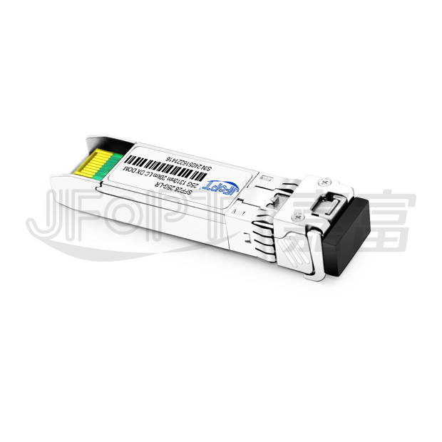
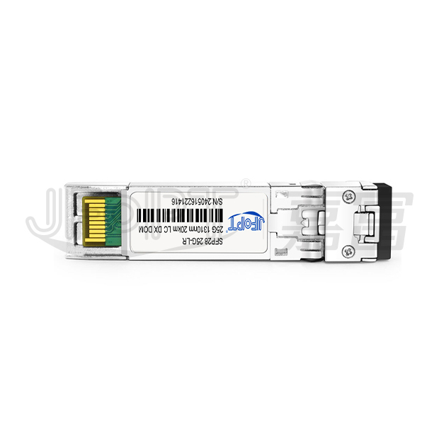
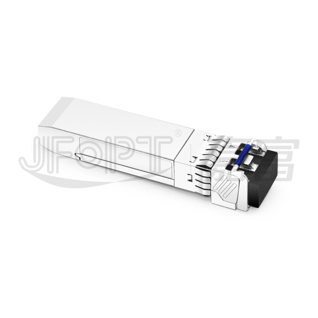
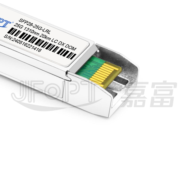
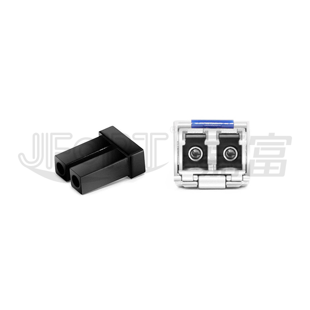
JFTSM-SFP28-25-13-20(LR)-LCD
|
Manufacturer brand
|
JFOPT
|
|
Package type
|
SFP28
|
Optical connector
|
Duplex LC
|
|
Max data rate
|
25.78G
|
Channel data rate
|
10.31Gbps
|
|
Effective transmission distance
|
20km
|
||
|
Wavelength
|
1310nm
|
Operating voltage
|
3.3V
|
|
Fiber type
|
SMF
|
Core size
|
9/125
|
|
Transmitter type
|
DFB-LD
|
Receiver type
|
CDR
|
|
TX power
|
-7~2dbm
|
Receiver sensitivity
|
<9.5dBm
|
|
Digital diagnostic monitoring(DDM)
|
YES
|
Receiver overload
|
2dBm
|
|
Power consumption
|
<1.2W
|
Protocols
|
SFF-8402
|
|
Operating temperature(Commercial)
|
0℃~+70℃
|
Storage temperature(Commercial)
|
-40℃~+85℃
|
|
Operating temperature(Industrial)
|
-40℃~+85℃
|
Storage temperature(Industrial)
|
-40℃~+85℃
|
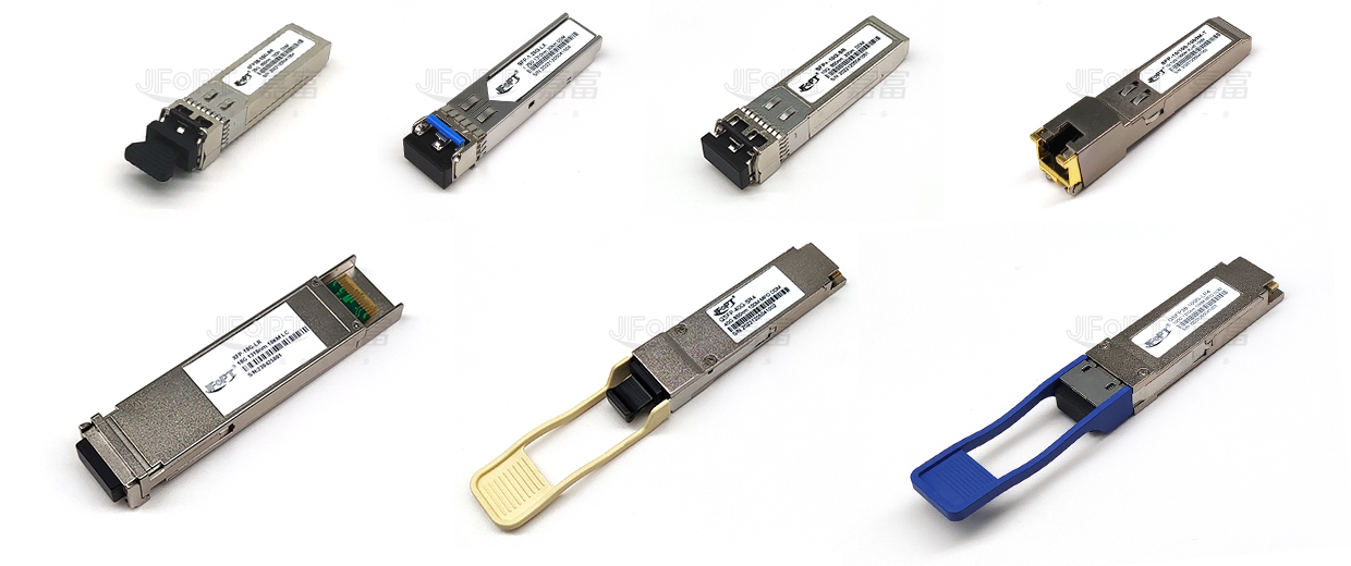
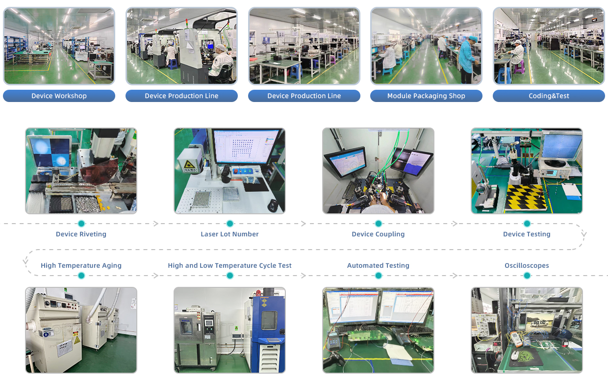
JFOPT continues to invest in optical transceiver production, covering a full range of optical transceiver such as 1*9, SFP, 10G, 25G, 100G, 200G, 400G, 800G GPON/EPON/XG/XGSPON OLT transceiver. At the same time, our company provides TOSA, ROSA, BOSA semi-finished device solutions for the downstream peer. JFOPT's production line has a daily production capacity of 10,000 optical transceivers and 20,000 optical devices. In addition, JFOPT's optical transceiver have industry-leading high temperature resistance and anti-interference capability, and are widely used in computing centers, operators, traffic security, power facilities and other industries.
The JFOPT SFP28 25G 1310nm 20km LR LC DX transceiver is a high-performance solution for duplex optical data communications, supporting data rates of 25.78Gbps. It features an SFP+ 20-pin connector for hot-pluggable capability and provides digital diagnostic monitoring through an I2C interface. The module includes built-in dual clock and data recovery (CDR) for enhanced signal integrity.Designed for single-mode fiber, this transceiver operates at a nominal wavelength of 1310nm. The transmitter section integrates a high-performance 1310nm DFB laser, compliant with Class 1 laser safety standards (IEC 60825). The receiver section is equipped with an InGaAs detector pre-amplifier (IDP) housed in an optical header, paired with a limiting post-amplifier IC for reliable and efficient performance.
| Single +3.3V power supply | Hot-pluggable | ||||||||
| Built-in dual CDR | Support 25.78 Gb/s data links | ||||||||
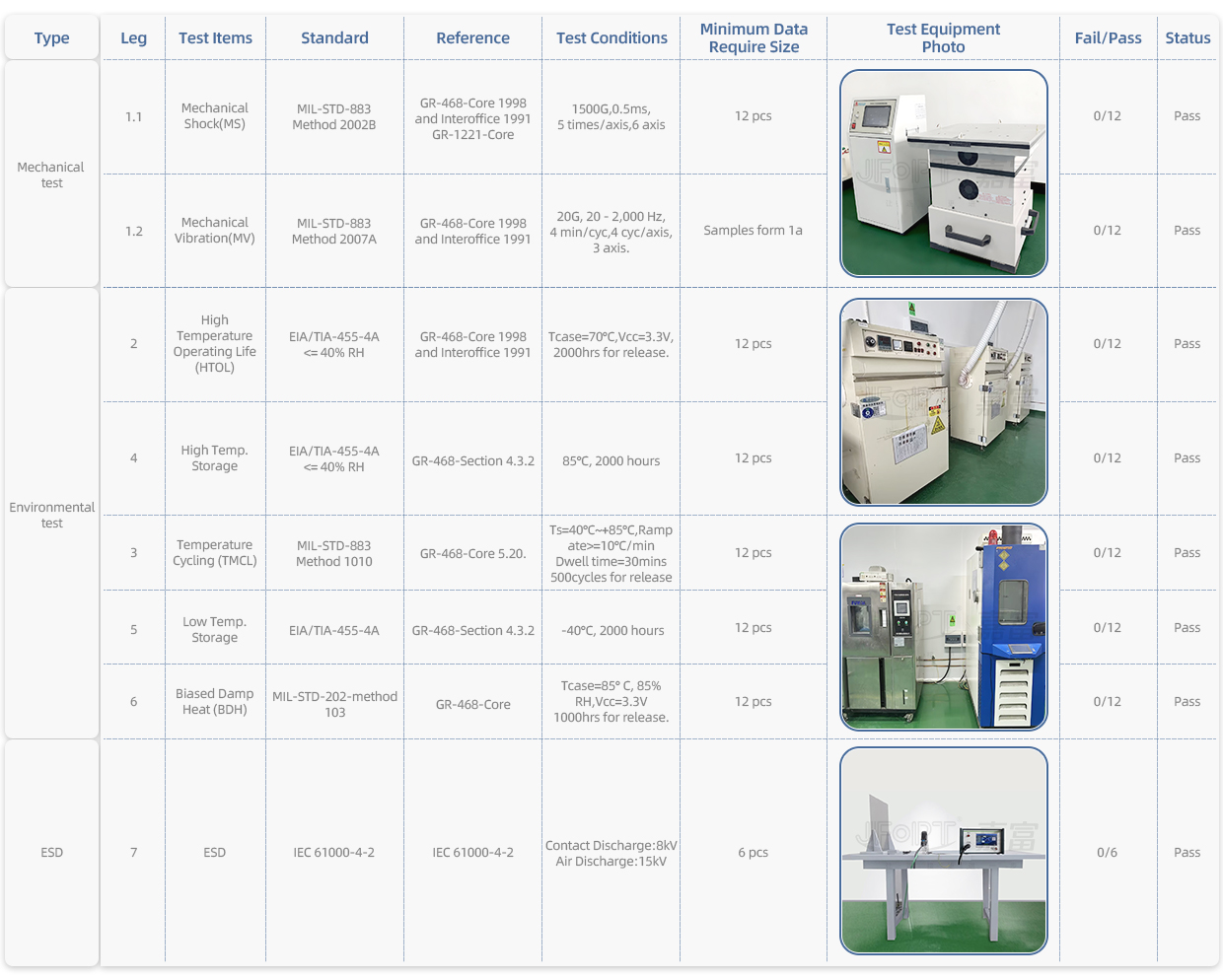
| Up to 20km on 9/125um SMF | Operating case temperature:-40~+85 | ||||||||
| Very low EMI and excellent ESD protection | Power dissipation < 1.2W |
| 25GbE | CPRI | ||||||||
| Other optical links |

| Parameter | Symbol | Unit | Min. | Max. | |||||
| Storage temperature range | Ts | °C | -45 | 85 | |||||
| Relative humidity | RH | % | 0 | 95 | |||||
| Input voltage | Vcc | V | 0 | 4 | |||||
| Parameter | Symbol | Unit | Min. | Typ. | Max. | ||||
| Operating case temperature range | Tc | ℃ | -45 | - | 85 | ||||
| Supply voltage | Vcc | V | 3.135 | 3.3 | 3.465 | ||||
| Bit rate | BR | Gb/s | - | 25.78125 | - | ||||
| Max supported link length | L | km | - | - | 20 | ||||
| Parameter | Symbol | Unit | Min. | Typ. | Max. | Note | |||
| Power dissipation | - | W | - | - | 1.2 | - | |||
Transmitter |
|||||||||
| Input differential impedance | RIN | Ω | - | 100 | - | - | |||
| Single ended data input swing | VIN | mVp-p | 90 | - | 450 | - | |||
| Tx_disable input voltage – low | VIL | V | -0.3 | - | 0.8 | - | |||
| Tx_disable input voltage – high | VIH | V | 2.0 | - | Vcc+0.3 | - | |||
| Tx_fault output voltage – low | VOL | V | -0.3 | - | 0.8 | - | |||
| Tx_fault output voltage – high | VOH | V | 2.0 | - | Vcc+0.3 | - | |||
Receiver |
|||||||||
| Output impedance (Differential) | Zout | V | - | 100 | - | - | |||
| Rx_LOS output voltage - low | VOL | V | -0.3 | - | 0.8 | - | |||
| Rx_LOS output voltage- high | VOH | V | 0.2 | - | Vcc+0.3 | - | |||
| Parameter | Symbol | Unit | Min. | Typ. | Max. | Note | |||
Transmitter |
|||||||||
| Center wavelength | λ | nm | 1295 | 1310 | 1325 | - | |||
| Data rate | B | Gb/s | - | 25.78 | - | - | |||
| Output spectral width | λ(-20dB) | nm | - | - | 1 | - | |||
| Optical output power | Po | dBm | -7 | - | 2 | - | |||
| Extinction ratio | ER | dB | 3.5 | - | - | - | |||
| Transmitterand dispersion penalty | TDP | dB | - | - | 3.2 | - | |||
Receiver |
|||||||||
| Operating wavelength | λ | nm | 1260 | - | 1355 | - | |||
| Overload | - | dBm | 2 | - | - | - | |||
| Receiver sensitivity (OMA) | POMA | dBm | - | - | -11.3 | - | |||
| Optical return loss | ORL | dB | - | - | -26 | - | |||
| Signal detect threshold-de-assert | SD | dBm | - | - | -14 | - | |||
| LOS hysteresis | - | dB | 0.5 | - | - | - | |||
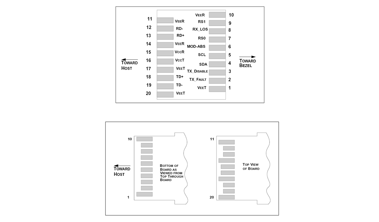
| Pin No. | Symbol | Logic | Description | ||||||
| 1,20 | VEET | - | Transmitter ground(common with receiver ground) | ||||||
| 2 | TX fault | LVTTL output | Transmitter fault. low normal operation, high fault indication | ||||||
| 3 | TX disable | LVTTL input | Transmitter disable. laser output disabled on high or open | ||||||
| 4 | SDA | LVTTL input/output | Module definition 2.data line for serial ID | ||||||
| 5 | SCL | LVTTL input/output | Module definition 1.clock line for serial ID | ||||||
| 6 | MOD-ABS | - | Module definition 0.grounded within the module | ||||||
| 7 | RS0 | LVTTL input | Rate select 0, optionally controls SFP28 module receiver. LVTTL logic. | ||||||
| 8 | LOS | LVTTL output | Loss of signal indication. Logic 0 indicates normal operation. | ||||||
| 9 | RS1 | LVTTL input | Rate select 1, optionally controls SFP28 module transmitter. LVTTL logic. | ||||||
| 10,11,14 | VEER | - | Receiver ground(common with transmitter ground) | ||||||
| 12 | RD- | CML output | Receiver inverted DATA out.AC coupled | ||||||
| 13 | RD+ | CML output | Receiver non-inverted DATA out.AC coupled | ||||||
| 15 | VCCR | - | Receiver power supply | ||||||
| 16 | VCCT | - | Transmitter power supply | ||||||
| 18 | TD+ | CML input | Transmitter non-inverted DATA in.AC coupled | ||||||
| 19 | TD- | CML input | Transmitter inverted DATA in.AC coupled | ||||||


 Ann
Ann


