


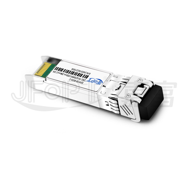
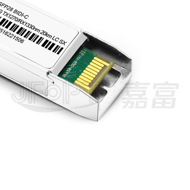
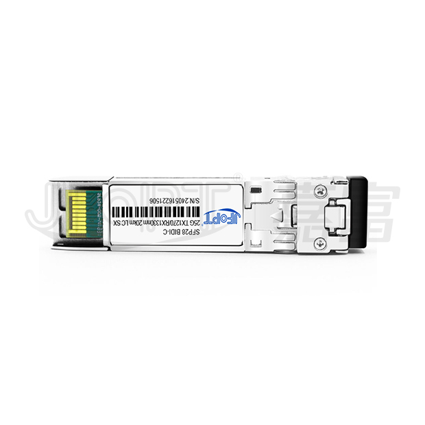

| Product model | JFTSM-SFP28BD-25-1213-20(ELR)-LC | Manufacturer brand | JFOPT |
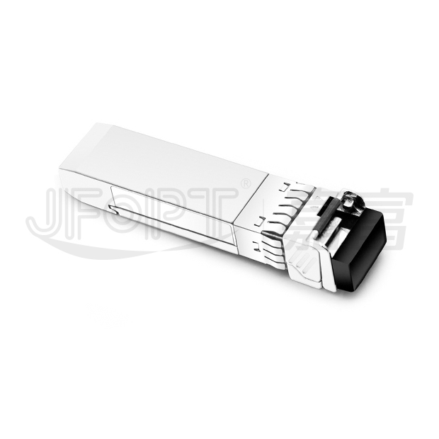
| Package type | SFP28 | Optical connector | Simplex LC |
| Max data rate | 25.78Gbps | Channel data rate | - |
| Effective transmission distance | 20km | ||
| Wavelength | 1270nm-TX/1330nm-RX | Operating voltage | 3.3V |
| Fiber type | SMF | Core size | 9/125 |
| Transmitter type | DFB BiDi | Receiver type | PIN |
| TX power | 0~6dBm | Receiver sensitivity | <-14dBm |
| Digital optical monitoring(DOM) | YES | Receiver overload | 2.5dBm |
| Power consumption | ≤1.2W | Protocols | eCPRI, SFF-8472, SFF-8432, SFF-8431 |
| Operating temperature(Commercial) | 0℃~+70℃ | Storage temperature(Commercial) | -40℃~+85℃ |
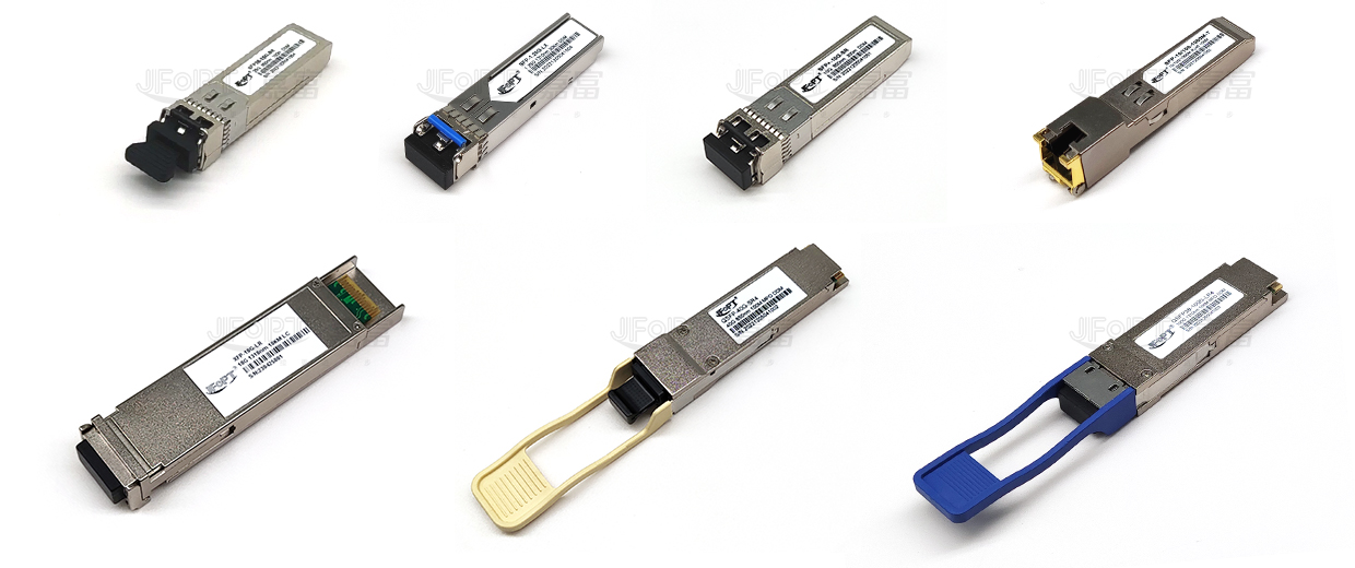
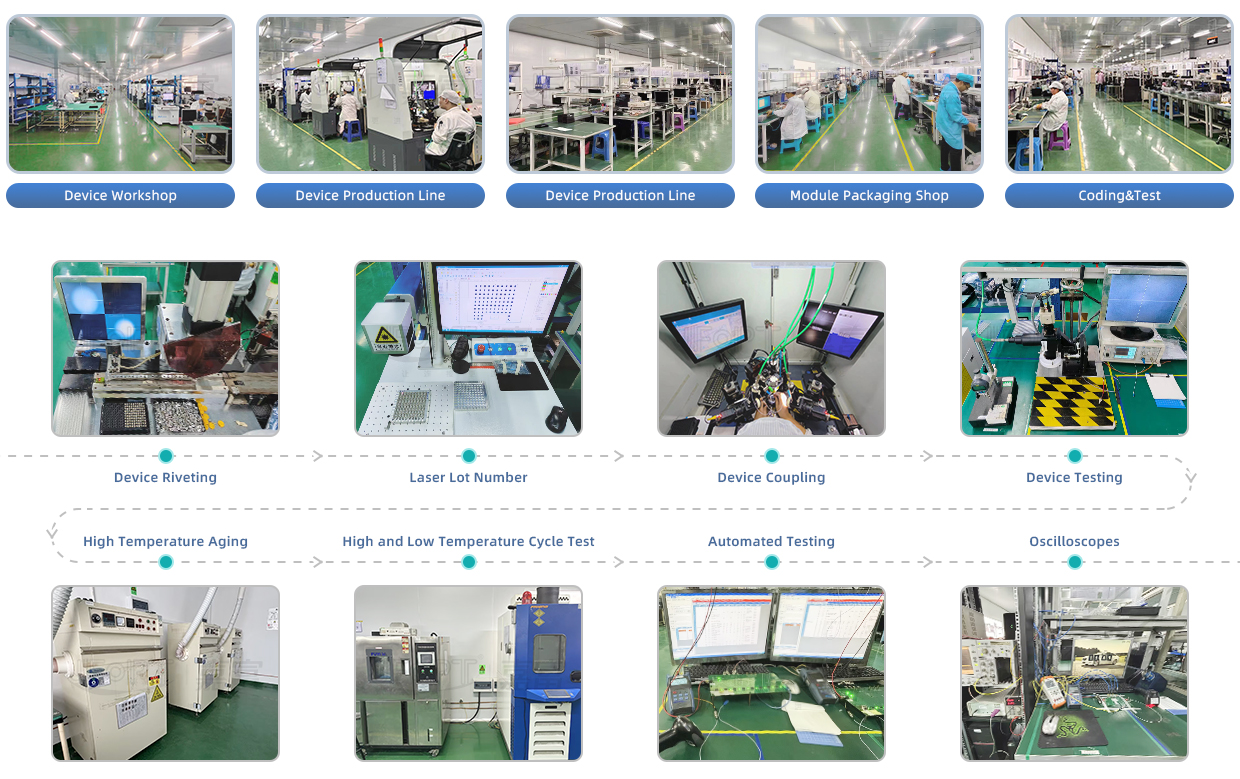
JFOPT continues to invest in optical transceiver production, covering a full range of optical transceiver such as 1*9, SFP, 10G, 25G, 100G, 200G, 400G, 800G GPON/EPON/XG/XGSPON OLT transceiver. At the same time, our company provides TOSA, ROSA, BOSA semi-finished device solutions for the downstream peer. JFOPT's production line has a daily production capacity of 10,000 optical transceivers and 20,000 optical devices. In addition, JFOPT's optical transceiver have industry-leading high temperature resistance and anti-interference capability, and are widely used in computing centers, operators, traffic security, power facilities and other industries.
The JFOPT SFP28 BIDI 25G 1270/1330nm 20km ELR LC SX transceiver is a high-performance module designed for bidirectional optical data transmission over single-mode fiber, supporting distances of up to 20km. It complies with SFF-8472, SFF-8402, SFF-8432, and applicable sections of SFF-8431 standards.Equipped with digital diagnostic monitoring via a 2-wire serial interface, as outlined in SFF-8472, this transceiver ensures reliable performance and precise monitoring for seamless integration into high-speed network applications.
| Up to 20 km transmission distance | LC single connector | ||||||||
| Low power consumption <1.2W | -40℃ to 85℃ operating case temperature range | ||||||||
| Single 3.3V±5% power supply | Compliant with SFF-8472 |
| 25GBASE-LR | CPRI option 10 / eCPRI | |||||||

| Form Factor | Data Rate(Gb/s) | Laser | Average Power (dBm) |
Detector | OMA Sensitivity 5E-5 (dBm) |
Top (℃) |
Reach (km) |
||
| SFP28 | 25.78125 | 1270nm DFB | 0~6 | PIN | <-14 | -40~85 | 20 | ||
| Parameter | Symbol | Unit | Min. | Max. | |||||
| Storage temperature range | TS | °C | -40 | 85 | |||||
| Relative humidity | RH | % | 0 | 85 | |||||
| Supply voltage | VCC | V | -0.3 | 3.6 | |||||
| Parameter | Symbol | Unit | Min. | Typ. | Max. | ||||
| Operating case temperature range | Tc | ℃ | -40 | - | 85 | ||||
| Power supply voltage | VCC | V | 3.135 | 3.3 | 3.465 | ||||
| Bit rate | BR | Gb/s | 24.33024 | 25.78125 | - | ||||
| Max. supported link length | L | km | 10 | 20 | - | ||||
| Parameter | Symbol | Unit | Min. | Typ. | Max. | Note | |||
| Supply voltage | VCC | V | 3.14 | 3.3 | 3.46 | - | |||
| Supply current | Icc | mA | - | - | 360 | @3.3V | |||
Transmitter |
|||||||||
| Input differential impedance | Rin | Ω | - | 100 | - | - | |||
| Single ended data input swing | VIN | mVp-p | 90 | - | 450 | - | |||
| Transmit disable voltage | VDIS | V | 2 | - | VCCHOST | - | |||
| Transmit enable voltage | VEN | V | VEE | - | VEE+0.8 | - | |||
| Transmit fault assert voltage | VFA | V | 2.2 | - | VCCHOST | - | |||
| Transmitfault de-assert voltage | VFDA | V | VEE | - | VEE+0.4 | - | |||
Receiver |
|||||||||
| Single ended data output swing |
VOD | mVp-p | 200 | - | 450 | - | |||
| LOS fault | VLOSFT | V | 2.2 | - | VccHOST | - | |||
| LOS normal | VLOSNR | V | VEE | - | Vee+0.4 | - | |||
| Parameter | Symbol | Unit | Min. | Typ. | Max | Notes | |||
Transmitter |
|||||||||
| Center wavelength range | λ | nm | 1320 | - | 1340 | Downstream | |||
| - | - | 1280 | Upstream | ||||||
| Spectral width | -20dB | - | nm | - | - | 1 | - | |||
| Side mode suppression ratio | SMSR | dB | 30 | - | - | - | |||
| Average launch power | PAVG | dBm | 0 | - | 6 | - | |||
| OMA launch power | POMA | dBm | -2 | - | - | - | |||
| Transmitter and dispersion penalty 25G | BER=5E-5 | TDP | dB | - | - | 4 | - | |||
| Average launch power of OFF transmitter |
POFF | dBm | - | - | -30 | - | |||
| Extinction ratio | ER | dB | 3.5 | - | - | - | |||
| RIN20OMA | RIN | dB/Hz | - | - | -130 | - | |||
| Optical return loss tolerance | - | dB | - | - | 20 | - | |||
| Mask margin | - | % | 5 | - | - | 1 | |||
Note 1: Template: {0.31, 0.40, 0.45, 0.34, 0.38, 0.40}, Hit Ratio: 5E-5 |
|||||||||
| Parameter | Symbol | Unit | Min. | Typ. | Max | Notes | |||
Receiver |
|||||||||
| Center wavelength | λr | nm | 1260 | 1270 | 1280 | Downstream | |||
| 1320 | 1330 | 1340 | Upstream | ||||||
| Overload | - | dBm | 2.5 | - | - | ||||
| OMA receiver sensitivity up to 25G 5E-5 | POMA | dBm | - | - | -14 | - | |||
| LOS de-assert | LOSA | dBm | -30 | - | - | ||||
| Los assert | LOSD | dBm | -17 | - | |||||
| Los hysteresis | - | dB | 0.5 | - | - | ||||

| Pin No. | Symbol | Logic | Description | ||||||
| 1 | VeeT | - | Connected to signal ground on the host board. | ||||||
| 2 | TX fault | LVTTL output | Module transmitter fault output | ||||||
| 3 | TX disable | LVTTL input | Module transmitter disable control | ||||||
| 4 | SDA | LVTTL input/output | 2-wire serial interface data | ||||||
| 5 | SCL | LVTTL input/output | 2-wire serial interface clock | ||||||
| 6 | MOD_ABS | - | Module absent (connected to Module ground) | ||||||
| 7 | RS0 | LVTTL input | Rate select 0 (Rx): Low=CDR Bypass; high=CDR select | ||||||
| 8 | LOS | LVTTL output | Receiver loss of signal | ||||||
| 9 | RS1 | LVTTL input | Rate select 1 (Tx): Low=CDR Bypass; high=CDR select | ||||||
| 10,11,14 | VeeR | - | Connected to signal ground on the host board. | ||||||
| 12 | RD- | CML output | Receiver inverted data output, internally AC coupled and terminated. | ||||||
| 13 | RD+ | CML output | Receiver non-inverted data output, internally AC coupled and terminated. | ||||||
| 15 | VccR | - | Receiver power 3.3V supply | ||||||
| 16 | VccT | - | Transmitter power 3.3V supply | ||||||
| 18 | TD+ | CML input | Transmitter non-inverted data input, internally AC coupled and terminated. | ||||||
| 19 | TD- | CML input | Transmitter inverted data Input, internally AC coupled and terminated | ||||||


 Ann
Ann


