


After years of development, fiber optic networks have gradually become widespread, shining brightly in the field of communications due to their advantages such as low electromagnetic interference, high data transmission rates, and excellent security. Nowadays, in many industrial application scenarios, traditional copper networks are gradually being replaced by fiber optic networks. Although acquiring fiber optic equipment has become relatively easy, designing a network is not a simple task. To ensure the overall integrity and performance of the network, we need to address a series of key factors.
Among them, fiber loss, as a factor often overlooked when deploying fiber optic networks, largely stems from engineers' lack of sufficient understanding. Fiber loss, or the loss of signals during transmission, directly affects the reliability of transmission. Therefore, it is crucial to accurately calculate fiber loss and take corresponding measures. Next, we will share some insights into calculating fiber loss and discuss how to effectively reduce fiber loss in the network to enhance overall performance.
Important Factors to Consider When Calculating Fiber Loss
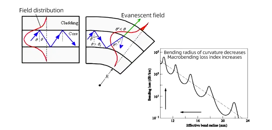
A small portion of fiber optic loss stems from the bending of the fiber, often due to improper cable handling. Bending can be classified into two types: macro-bending and micro-bending. Macro-bending refers to larger bends in the cable, while micro-bending refers to the smaller bends.
Formulas for Calculating Fiber Optic Loss
Practical Tips to Reduce Fiber Optic Loss in Networks
Designing a fiber optic system is not an easy task; it is a balancing act that should address all system factors that could potentially cause loss. Fiber loss is caused by a series of intrinsic and extrinsic factors. Fiber loss, or signal loss, also known as fiber attenuation, is caused by the intrinsic and extrinsic characteristics of both single-mode and multimode fibers. To understand how to calculate fiber loss in a network, these factors must be addressed.
Here are some factors to consider when budgeting for fiber loss calculations:
The term inherent attenuation loss encompasses three main types of losses, namely absorption loss, scattering loss, and dispersion loss.
Scattering loss occurs mainly due to fluctuations in fiber composition, differences in material density, potential defects during manufacturing, and minor structural irregularities. These variations typically manifest at a microscopic level and are key factors contributing to scattering loss.
Dispersion loss, on the other hand, manifests as distortion of the optical signal during fiber transmission. Dispersion loss can be categorized into two types: intramodal and intermodal. Intramodal dispersion is primarily caused by pulse spreading in single-mode fibers due to variations in propagation constants or refractive indices along the fiber length. Conversely, intermodal dispersion arises from differences in propagation speeds between different modes in multimode fibers, resulting in pulse broadening.
Absorption loss is another significant contributor to optical loss in fiber cables. During the transmission of light, photons interact with various glass components, metal ions, or electrons within the fiber. In these interactions, light energy is absorbed and converted into other forms of energy, such as heat, wavelength impurities, and molecular resonances.
Specifically, for multimode fibers with specifications of 50/125µm and 6.25/125µm, the intrinsic attenuation at a wavelength of 850 nanometers is 3.5 dB/km. For single-mode fibers with a specification of 9µm, the intrinsic attenuation at wavelengths of 1310 nanometers and 1550 nanometers is 0.4 dB/km and 0.3 dB/km, respectively. These data provide important reference points for the performance of fiber optics.
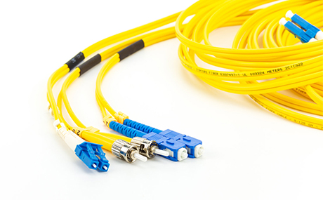
Insertion loss, also known as connector loss, refers to the optical power loss incurred when inserting devices into fiber optic cables or transmission lines. Typically, factory pre-assembled single-mode connectors exhibit insertion losses ranging from approximately 0.1 to 0.2 dB, while field-terminated connectors may have insertion losses ranging from 0.2 to 1.0 dB. In comparison, the insertion loss range for multimode connectors is typically between 0.2 and 0.5 dB.
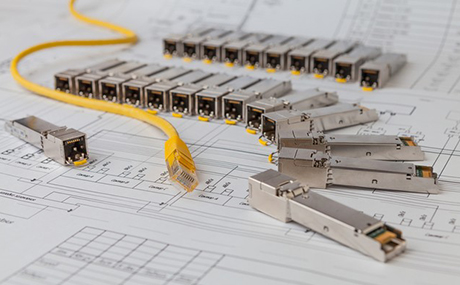
In fiber optic networks, laser transmitters and LED transmitters are two crucial types of transmitters. Laser transmitters are categorized into three types based on the distance they cover: low, medium, and high, corresponding to short-distance, medium-distance, and long-distance transmitters. LED transmitters, on the other hand, come in standard and high-power options. The selection of transmitters needs to match the type of fiber being used, and attention should be paid to the optical output at the connector, with -5 dB being the most common optical output value.
For fiber type selection, most networks adopt either single-mode or multimode fiber, or a combination of both. The attenuation factor for multimode fiber typically ranges between 2.5 dB/km (@850nm) and 0.8 dB/km (@1300nm), while for single-mode fiber, it is 0.25 dB/km (@1550nm) and 0.35 dB/km (@1310nm). Single-mode fiber is compatible with laser transmitters and suitable for various distance types, while multimode fiber is often used with LED transmitters, although its transmission distance usually does not exceed 1 kilometer due to energy limitations. It is worth noting that high-power LED transmitters can also be used with single-mode fiber.
Fiber optic attenuation coefficients are defined by manufacturers and are measured in dB/km. To calculate fiber optic attenuation, simply multiply the attenuation coefficient by the total length of the fiber optic cable. Here, the length refers not only to the network distance but the overall length of the fiber optic cable.
Redundancy is a broad term encompassing multiple factors, including aging of receiver and transmitter components, fiber aging, cable twisting and bending, potential for future equipment expansion, and added connectors for repairing cable breaks. Typically, redundancy in fiber optic loss budgeting is maintained between 3 to 10 dB.
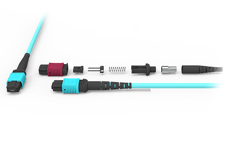
Fiber optic fusion splicing is a technique used to connect the ends of fiber optic cables, aiming to ensure that the optical intensity passing through the cable is equivalent to that of a single fiber. In fiber optic cable networks, mechanical connectors and fusion splices are two important connector types. Mechanical connectors use connector assemblies at the ends of fiber optics for connection, while fusion splices directly splice the ends of fiber optics together. Generally, the loss for mechanical connectors ranges from 0.1 to 1.5 dB per connector, while for fusion splices, it is typically between 0.1 to 0.5 dB per splice. Due to its lower loss coefficient, fusion splicing is more popular in practice.
A small portion of fiber optic loss stems from the bending of the fiber, often due to improper cable handling. Bending can be classified into two types: macro-bending and micro-bending. Macro-bending refers to larger bends in the cable, while micro-bending refers to the smaller bends.
These formulas will help us consider multiple factors to arrive at a more accurate loss estimate.
Firstly, total link loss is determined by fusion splice loss, cable attenuation, connector loss, and safety redundancy factors. Specifically:
Fusion splice loss (dB) is calculated by multiplying the fusion splice loss tolerance (dB) by the number of splices.
Cable attenuation (dB) is the product of the maximum cable attenuation coefficient (dB/km) and the cable length.
Connector loss (dB) is obtained by multiplying the connector loss tolerance (dB) by the number of connectors.
It's important to note that while these formulas provide a framework for calculating fiber optic loss, actual loss values may deviate due to various factors. Therefore, in practical applications, we need to exercise caution and adjust estimates as needed.
To illustrate the application of these formulas with a specific example: Let's assume we have a single-mode link that is 40 kilometers long, with 5 splices and 2 pairs of connectors. Using the formulas:
Cable attenuation (dB) is 40 km multiplied by 0.4 dB/km.
Fusion splice loss is 0.1 dB/km multiplied by 5.
Connector loss is 0.75 dB multiplied by 2.
Adding a safety margin of 3.0 dB.
By summing up these values, we can estimate the link loss. In this example, transmitting over the fiber link requires a minimum power of 21 dB. However, after setting up the network, it's essential to measure and verify the link loss to promptly identify and address any potential performance issues.
To ensure long-term stability and performance of the network, it's crucial to allocate sufficient performance margin to account for potential performance degradation over time. This ensures that the optical power output remains within the effective range of receiver sensitivity. To minimize fiber optic loss in the network to the greatest extent possible, the following measures can be taken during the design and installation of fiber optic links:
Firstly, ensure the use of high-quality cables throughout the network, with cables exhibiting similar performance characteristics to ensure consistency in transmission.
Secondly, endeavor to use certified connectors, ensuring that insertion loss is below 0.3 dB, with additional loss not exceeding 0.2 dB, to safeguard signal integrity and clarity.
During fusion splicing operations, strict adherence to environmental and splicing requirements is essential to ensure splice quality and reduce losses resulting from improper splicing.
Furthermore, maintaining cleanliness of connectors is crucial, as any minute contamination can potentially impact signal transmission.
When laying optical cables, opt for the best laying methods to avoid unnecessary bending and twisting, thus minimizing fiber optic loss.
Simultaneously, strive to utilize full reels of optical cables for deployment, with reel lengths exceeding 500 meters, to reduce the number of joints and consequently lower losses attributed to joints.
To ensure the stable operation of the network, install protection measures against environmental factors such as electrical, lightning, mechanical, and corrosion.
Finally, opt for high-quality components, including cables, connectors, transmitters, media converters, switches, etc., as the performance of these components directly impacts the performance of the entire network. High-quality components aid in performance enhancement and maximize the reduction of fiber optic losses.
In summary, addressing fiber optic link losses is crucial in the design and setup of fiber optic networks, involving considerations across various aspects. This article extensively explores these considerations, along with methods for calculating fiber optic losses and techniques for minimizing them. While preventive measures against fiber optic losses can be taken through calculations, the installation of high-quality equipment and cables remains indispensable.


 Ann
Ann


