


Polarity Overview
A fiber optic link’s transmit signal (Tx) at end of the cable must match the corresponding receiver (Rx) at the other end. So, what is fiber polarity? Fiber polarity could be defined as the direction light signals travel from one end to the other end of an optical fiber cable.
Before introducing MPO/MTP patch cord, let’s learn about the polarity of duplex patch cord (Please refer to JFOPT specification
Polarity of Duplex Patch Cord
Type A-B:
Connector A on the left end linked to Connector B on the right end and Connector B on the left end linked to Connector A on the right end.

Type A-A:
Connector A on the left end linked to Connector A on the right end and Connector B on the left end linked to Connector B on the right end.

Polarity of MPO/MTP Patch Cord
It becomes a bit more complex when dealing with multi-fiber MPO/MTP patch cord. Industry standards defines 3 different polarity methods for MPOs—Method 1, Method 2, and Method 3. And each method uses different types of MPO cables.
Type A:
A key-up-connector A on one end and a key-down-connector B on the other end so that the fiber located in Position 1 (Connector A Tx) arrives at Position 1 (Connector B Rx) at the other end, as well as Position 2 (Tx) arrives at Position 2 (Rx), Position 3 (Tx) arrives at Position 3 (Rx), …, Position 12 (Tx) arrives at Position 12 (Rx).

Type B:
The key-up-connector A and B on both sides to achieve the flip so that the fiber located in Position 1 (Connector A Tx) arrives at Position 12 (Connector B Rx) at the other end, as well as Position 2 (Tx) arrives at Position 11 (Rx), Position 3 (Tx) arrives at Position 10 (Rx), …, Position 12 (Tx) arrives at Position 1 (Rx).

Type C:
A key-up-connector A on one end and a key-down-connector B on the other end like type A, but each pair of fibers is flipped so that the fiber located in Position 1 (Connector A Tx) arrives at Position 2 (Connector B Rx) at the other end, as well as Position 2 (Tx) arrives at Position 1 (Rx), Position 3 (Tx) arrives at Position 4 (Rx), Position 4 (Tx) arrives at Position 3 (Rx), …, Position 11 (Tx) arrives at Position 12 (Rx), Position 12 (Tx) arrives at Position 11 (Rx).

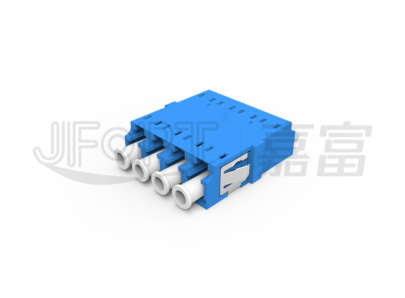
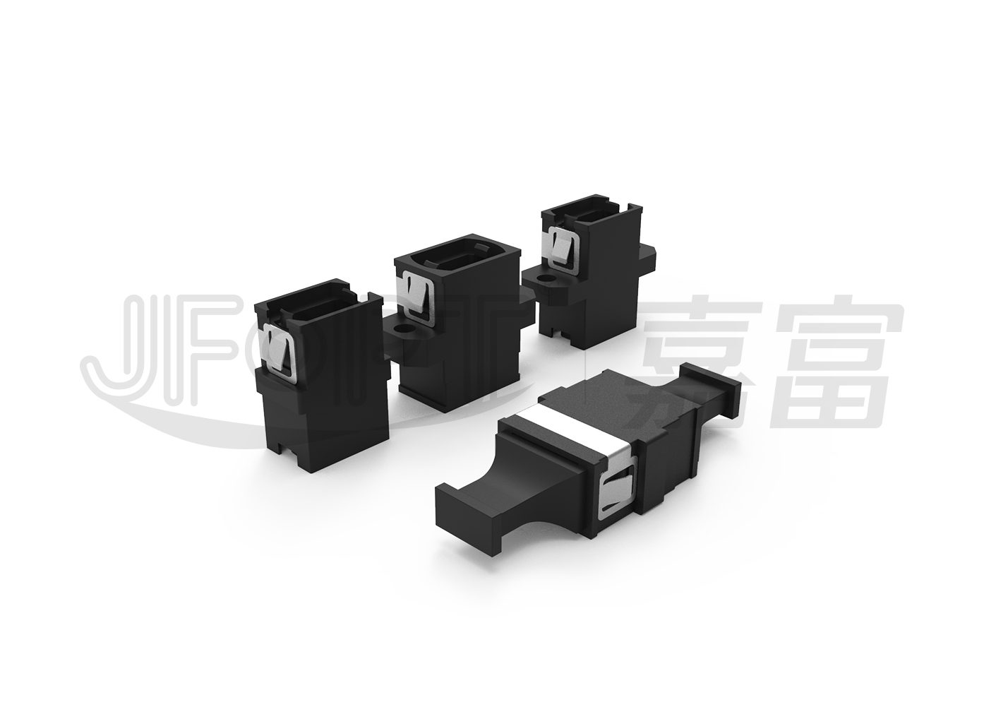
Polarity of MPO/MTP Adapter
There are two types of MPO/MTP adapter, A and B.
Type A:
Type A adapter is used to mate a key-up-connector and a key-down-connector.

(Mating Diagram of Polarity A Adapter1)

(Mating Diagram of Polarity B Adapter2)
Type B:
Type B adapter is used to mate both key-up-connectors.

(Mating Diagram of Polarity B Adapter1)

(Mating Diagram of Polarity B Adapter2)
MPO/MTP Cassette – The basic unit to achieve modular connection
The MPO/MTP cassette is usually composed of metal shell, MPO/MTP breakout patch cord, MPO/MTP adapter and duplex adapter.

The advantage & disadvantage of various polarities of MPO/MTP in application
Application 1: High-density data center
MPO/MTP patch cord is applied in HD data center to simplify the cabling and reduce the quantity of patch cords. Let’s see what effects can be achieved by using MPO/MTP patch cords with different polarities.
1.Type A MPO/MTP Patch Cord
From the below figure, when MPO/MTP patch cord with polarity A is installed, through MPO cassette with type A MPO adapter, the devices should be connected with one A-B duplex patch cord and one A-A duplex patch cord. This may cause confusion in the application and hard to maintain.

2.Type B MPO/MTP Patch Cord
From the below figure, when MPO/MTP patch cord with polarity B is installed, through MPO cassette with type A MPO adapter, the devices can be connected with two A-B duplex patch cords. It is easy to manage and maintain. However, 2 different pin-out-cassettes have to be required.

3.Type C MPO/MTP Patch Cord
From the below figure, when MPO/MTP patch cord with polarity C is installed, through MPO cassette with type A MPO adapter, the devices can be connected with two same A-B duplex patch cords and two same MPO/MTP cassettes. It is easier to manage and maintain. But this link cannot be improved to be 40G/100G.

40/100G Data Center
In 40G/100G networking, MPO/MTP patch cord with polarity A and polarity B is used.
1.Hybrid connection of MPO/MTP patch cord with Polarity A and Polarity B
As shown in the figure below, B polarity MPO/MTP patch cord is used for the backbone, and polarity A MPO/MTP patch cords are used to link the devices and ODF, and they are mated by A polarity MPO/MTP adapters. Or the A-polarity MPO/MTP patch cord is used for the backbone, the A-polarity and B-polarity MPO/MTP jumpers are required to be used for the devices at both ends to the ODF respectively.

2.Pure Polarity B MPO/MTP Patch Cords
As shown in the figure below, all the MPO/MTP patch cords in the link is polarity B, as well as the MPO/MTP adapter. All the components have the uniform polarity for easy cabling and maintenance. However, APC polishing is not suitable for this cabling method.

To upgrade from a 10G network to a 40/100G network, the above two wiring methods are usually adopted. Why can't the MPO/MTP patch cord with polarity C be upgraded to 40/100G network? Let's take the 40G network as an example. In 40G networking, only 8 fibers are in use to send and receive signals (1-4 fibers for receiving, 9-12 fibers for transmitting). The light transmitting and receiving in QSFP transceiver is as shown in the figure below:

The left transceiver position 12 (Tx1) to link the right transceiver position 1 (Rx1), left position 11 (Tx2) to right position 2 (Rx2), left position 10 (Tx3) to right position 3 (Rx3), left position 9 (Tx4) to right position 4 (Rx4). While using polarity C MPO/MTP patch cords for wiring, the link can only be the left position 12 (Tx1) to the right position 11 (Tx2), the left position 11 (Tx2) to the right position 12 (Tx1). The transceiver link will be failed. That is why the high-density network that adopt MPO/MTP path cords with polarity C for wiring cannot be upgraded to 40/100G.


 Ann
Ann


